Remote Electrical Condition Monitoring: What Fixed Sensors Can Reveal Between Inspections
Remote electrical condition monitoring combines permanently installed sensors, a gateway and retained records. It keeps selected conditions visible between inspections and can notify an accountable person when a documented review rule is met.
The evidence covers only the named sensor points and supported conditions. Useful monitoring also preserves time, communications state, data gaps, alert ownership and the action taken after review.
Fixed sensorsData continuityOwned response
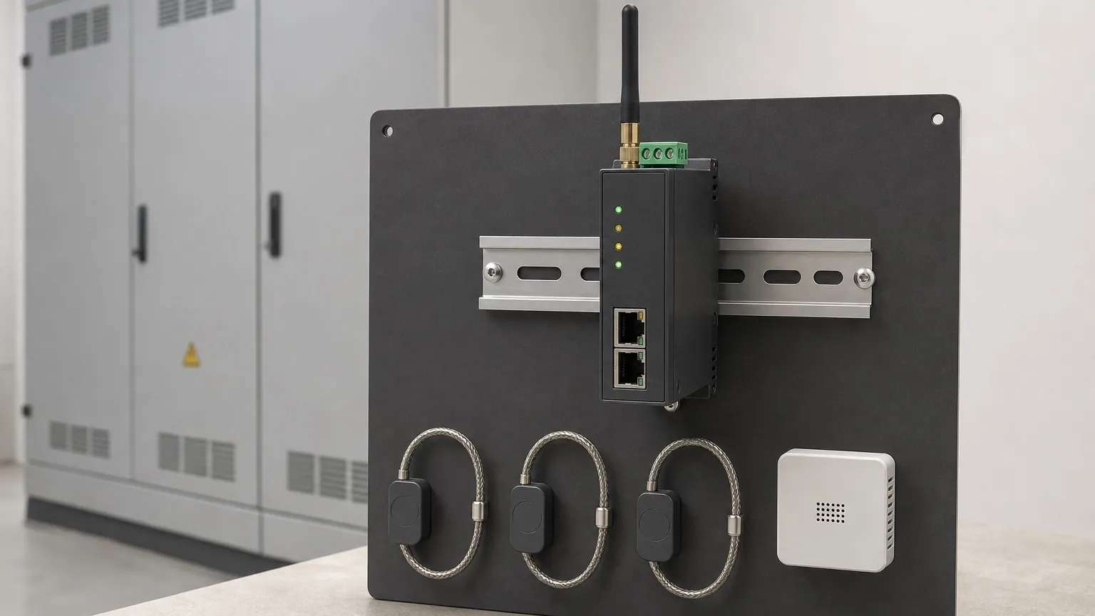
Recognition view: the gateway receives records from selected condition sensors before the data is buffered, exported and assigned to an alert owner.
01 · What the system is
A fixed sensor preserves one selected condition at one named point.
The sensor may observe connection temperature, enclosure humidity, device position or another supported indicator. A gateway timestamps and retains the record, while a local or remote platform presents trends, data quality and alerts.
A platform can combine several systems. The sensor type and point register still determine which physical condition each record represents.
Fixed condition monitoring
Preserves selected condition indicators continuously at installed points.
Useful when change between visits or unattended operation shapes the risk.
Records electrical quantities such as power and energy at named distribution boundaries.
Useful for baselines, branch comparison, allocation and energy verification.
ISO 17359:2018 provides general procedures for condition-monitoring programmes. ISO 13374-1 describes information-processing, communication and presentation functions for condition-monitoring systems.
02 · What can be monitored
Each sensor point needs a condition question and a decision owner.
Coverage follows the failure indicator or operating uncertainty the site needs to observe. A temperature sensor, environmental sensor and device-state input produce different evidence and leave different parts of the asset unseen.
01
Connection temperature
Evidence retainedA contact sensor retains the apparent temperature at one named electrical connection or supported surface.
Context requiredCurrent, operating state, comparable phases and ambient condition help explain whether a change deserves review.
Decision valueA persistent separation can prioritize inspection of the represented connection during an approved maintenance window.
02
Enclosure temperature and humidity
Evidence retainedAn environmental sensor records the conditions around supported switchgear or inside a designated enclosure zone.
Context requiredVentilation state, door condition, weather, room cooling and the sensor position remain attached to the trend.
Decision valueSustained heat, humidity or condensation risk can prompt environmental checks before deterioration progresses.
03
Device position and operation state
Evidence retainedCompatible auxiliary contacts or protection devices can retain open, closed, trip, transfer or operation-count records.
Context requiredThe point register identifies the device, state source, time basis and event sequence represented by each change.
Decision valueThe record supports event reconstruction, response checks and maintenance planning for the named mechanism.
04
Specialist condition indicators
Evidence retainedSupported architectures may add insulation-decomposition, partial-discharge, breaker-health or other specialist indicators.
Context requiredEach indicator keeps its own sensor boundary, measurement method, confidence and confirmation requirement.
Decision valueA specialist alert can justify a focused survey or planned inspection when the installed method supports that conclusion.
03 · From sensor to retained record
The monitoring chain has separate measurement, data and response states.
The sensor produces a value at a named point. The gateway attaches identity, time and quality information, then buffers and transfers the record. The final stage assigns an alert to a person who can review the evidence and record an action.
Solid arrows show the information sequence. Each shaded band represents a different system responsibility. The diagram omits installation terminals, energized access and network configuration details.
Measurement state
Confirms which sensor, point, value, unit and quality flag created the record.
Data state
Shows whether samples were buffered, transferred, synchronized or unavailable.
Response state
Preserves the review rule, recipient, acknowledgement and selected next action.
04 · Reading an alert
A condition alert remains attached to load, environment and data availability.
Read the connection-temperature lane first, then compare the current and ambient context. The communications lane shows whether the record remained available through a transfer outage. The final lane identifies when the site-specific review rule was met and who accepted responsibility.
Condition trend
The connection-temperature lane rises gradually at one named point. The displayed values belong to that sensor and period.
Operating context
Current increases during refrigeration demand, while enclosure temperature and humidity remain comparatively stable.
Communications state
A short network outage interrupts transfer. The gateway continues recording locally and synchronizes the buffered interval later.
Response state
The site-specific review rule creates an alert, records acknowledgement and preserves the planned inspection owner.
All values, traces and review rules are illustrative. The figure follows common condition-trending conventions using temperature in degrees Celsius, current in amperes, environmental context, communications status and an owned alert record. It provides no universal temperature or humidity limit.
05 · Data continuity and alarm ownership
A missing record and a healthy condition require different status messages.
Reliable monitoring identifies sensor faults, gateway interruptions and communications loss explicitly. It also records who receives an alert, when it was acknowledged and which operating response followed.
01
Sensor state
The point register shows the last valid sample, sensor status, battery or self-power condition where applicable, and any failed quality check.
The owner can distinguish a measured normal condition from an unavailable or doubtful sensor.
02
Gateway and clock
The gateway retains device identity, timestamps, time zone, synchronization status, storage capacity and configuration version.
A later reader can place the record on the same timeline as operator notes, protection events and maintenance work.
03
Communications loss
The platform records the last contact and identifies whether local buffering continued while the network path was unavailable.
Missing transfer is treated as a monitored fault state. It is never displayed as evidence of healthy equipment.
04
Alert ownership
Every alert records its recipient, acknowledgement, escalation time, operating consequence and chosen next action.
The monitoring system supports a response process instead of leaving an unattended notification in a dashboard.
06 · Cold-storage property example
One connection trend changed while refrigeration demand remained visible.
A cold-storage and logistics property relied on a secondary electrical room with limited daily staffing. Fixed sensors followed selected feeder connections and enclosure conditions. Existing metering supplied current context for the critical refrigeration feeder.
One connection-temperature record gradually separated from comparable points during recurring refrigeration demand. Room temperature and humidity remained stable enough for the change to deserve review.
01
Condition record
The named point separated gradually while current and room conditions remained attached to the same timeline.
02
Buffered interruption
A short internet outage stopped transfer. The gateway retained the samples locally and synchronized them after communications returned.
03
Owned response
The site-specific rule created an alert, recorded acknowledgement and assigned a qualified inspection before the next peak period.
04
Physical confirmation
Inspection established a degraded connection condition and defined the corrective scope. The sensor record had focused the inspection; it had not identified the condition automatically.
05
Comparable verification
After correction and restoration, the same point remained aligned with comparable connections under a similar refrigeration load.
The site, trend and response sequence are illustrative. Actual sensor selection, review rules, access controls, inspection method and corrective decision follow the equipment, design and operating consequence.
07 · What the evidence can change
Retained condition evidence can focus inspection and verify the result.
A trend or alert has practical value when it changes inspection priority, maintenance timing or verification. The action remains connected to the represented point and the conditions that made the comparison credible.
01
Recorded evidenceOne named connection develops a repeatable temperature separation under comparable load.
Investigation or actionPrioritize qualified inspection of that represented point during an appropriate maintenance window.
VerificationRetain the post-work trend under comparable load and confirm whether the separation recurs.
02
Recorded evidenceEnclosure humidity remains elevated during known ventilation or cooling states.
Investigation or actionReview the room, enclosure seals, ventilation and environmental controls that influence the sensor location.
VerificationCompare the same environmental point after the confirmed condition is addressed.
03
Recorded evidenceA device-state change and operating alarm share the same trusted timestamp.
Investigation or actionUse the sequence to focus protection, control or mechanism review around the named equipment.
VerificationConfirm the intended state sequence after approved corrective work and restoration.
04
Recorded evidenceA sensor, gateway or communications path stops reporting.
Investigation or actionRestore monitoring coverage and mark the affected interval as unavailable before interpreting asset condition.
VerificationConfirm sample continuity, clock alignment, local buffer recovery and platform synchronization.
08 · Choosing an architecture
Sensor coverage, retained evidence and response scope shape the system choice.
A limited environmental system can answer one enclosure-risk question. Connection-temperature monitoring adds selected thermal points and operating context. Integrated switchgear systems can combine device, protection and specialist condition data across several bays.
Architecture
Where it fits
Complete system
Neutral examples
Indicative hardware
Environmental monitoring starter
Selected electrical rooms or enclosures where temperature and humidity trends support a known environmental risk question.
Environmental sensors, compatible gateway, time source, local buffer, export, basic alert routing and a named point register.
Schneider PowerLogic CL110 with Panel Server and comparable environmental monitoring architectures.
8,000–20,000 MAD
Connection-temperature monitoring
Critical switchgear connections where fixed contact sensors and load context can expose a developing thermal separation.
Contact-temperature sensors, gateway, current or operating context, retained trends, site-specific alert rules and response ownership.
Schneider PowerLogic TH110 or HeatTag families and comparable fixed thermal-monitoring systems.
15,000–40,000+ MAD
Integrated switchgear condition monitoring
Multi-bay or critical installations combining breaker state, temperatures, protection data and supported specialist indicators.
Asset sensors, protection-device data, edge processing, local and remote interfaces, historian, diagnostics, permissions and service integration.
ABB SWICOM; Siemens SIMARIS control and supported condition-monitoring modules.
Project-priced
Environmental monitoring starter
Selected electrical rooms or enclosures where temperature and humidity trends support a known environmental risk question.
Complete system: Environmental sensors, compatible gateway, time source, local buffer, export, basic alert routing and a named point register.
Schneider PowerLogic CL110 with Panel Server and comparable environmental monitoring architectures.
8,000–20,000 MAD
Connection-temperature monitoring
Critical switchgear connections where fixed contact sensors and load context can expose a developing thermal separation.
Complete system: Contact-temperature sensors, gateway, current or operating context, retained trends, site-specific alert rules and response ownership.
Schneider PowerLogic TH110 or HeatTag families and comparable fixed thermal-monitoring systems.
15,000–40,000+ MAD
Integrated switchgear condition monitoring
Multi-bay or critical installations combining breaker state, temperatures, protection data and supported specialist indicators.
Complete system: Asset sensors, protection-device data, edge processing, local and remote interfaces, historian, diagnostics, permissions and service integration.
ABB SWICOM; Siemens SIMARIS control and supported condition-monitoring modules.
Project-priced
Indicative July 2026 MAD equivalents for hardware acquisition, using approximately 1 EUR = 10.71 MAD. VAT, import, transport, enclosure integration, communications, platform subscriptions, licenses, cybersecurity configuration, commissioning, calibration, training and professional analysis may be excluded. Integrated multi-bay systems remain project-priced because public component prices do not represent the engineered installation.
Examples support recognition and scope review; they are not rankings. Official references include Schneider PowerLogic TH110, CL110, ABB SWICOM and current Siemens SIMARIS control documentation.
09 · Complete system and commissioning record
Commissioning connects every point to data ownership and a response route.
The working system includes sensors, gateway, power, clock, local storage, communications, platform access, exports, licensing and alert responsibilities. Qualified personnel select and install sensing points under the approved equipment and site method.
Cybersecurity responsibilities cover network segmentation, approved protocols, credentials, user roles, remote access, updates and response to system changes. The owner should retain enough documentation to review or transfer the monitoring system later.
Monitoring question
Named asset, represented condition, operating consequence, evidence required and responsible owner.
Point and sensor register
Sensor type, asset location, point name, supported range, physical boundary, firmware and calibration or function-check record.
Gateway and retention
Gateway identity, local storage, clock source, time zone, sampling basis, buffer behavior and restoration after power or network loss.
Communications and security
Network path, approved ports and protocols, credentials, user roles, update responsibility, remote access and cybersecurity ownership.
Platform and export
Trend and event access, raw export, data retention, licensing, owner access, backup and an exit route if the platform changes.
Site, switchboard, feeder or device, exact sensor identity and the condition represented.
Data identity
Quantity, unit, sampling basis, timestamp, quality flag, load or environmental context and comparable history.
System state
Sensor health, gateway status, communications availability, buffered intervals, synchronization and data gaps.
Alert record
Site-specific review rule, event time, recipient, acknowledgement, escalation and operating consequence.
Interpretation
Supported finding, unavailable boundaries, alternative explanations and qualified confirmation still required.
Action and verification
Inspection, physical finding, corrective work, restoration and comparable post-work record.
IEC 62443-2-1:2024 addresses security-program requirements for asset owners, while IEC 62443-3-3 defines system security requirements and security levels. The applicable architecture and responsibilities depend on the site, connected systems and risk assessment.
Practical FAQ
Questions that often remain after a monitoring proposal.
These answers clarify platform integration, neighboring tools, coverage, communications loss and the limits of a normal dashboard status.
Often, when the sensors and gateway support a compatible protocol and the receiving system can preserve the required timestamps, quality states and point names. Integration scope, cybersecurity, alarm ownership and export access still need confirmation. The BMS or SCADA displays the record; the installed sensor defines the condition being observed.
Permanent energy metering records electrical quantities such as power and energy at named distribution boundaries. Condition monitoring follows selected indicators such as connection temperature, humidity or device state. One platform may collect both, while each sensor and measurement point retains a different purpose and boundary.
Fixed sensors preserve trends at selected contact points or supported surfaces. Thermography provides a wider apparent surface-temperature image during a qualified inspection. The methods can complement each other because fixed monitoring offers continuity and thermography can examine accessible areas outside the installed sensor set.
Coverage should follow asset criticality, known failure indicators, accessibility, operating consequence and the decision the record will support. Selected points on critical or lightly staffed equipment may deliver more useful evidence than broad coverage with no response owner.
A suitable architecture identifies the loss of contact and may retain records in a local buffer for later synchronization. Buffer duration and recovery behavior vary by gateway and configuration. Any unavailable interval remains visible and cannot be interpreted as a healthy equipment condition.
It establishes only that the selected points produced records that did not trigger the configured review rules during that period. Uninstrumented connections, unsupported failure modes, sensor faults and inaccessible conditions remain outside the evidence. Inspection and other tests still support the wider asset decision.
Conclusion
What continuous condition evidence makes possible.
A well-designed monitoring system can reveal when a selected condition changes, preserve the operating context, keep data gaps visible and assign the resulting alert to a person who can act.
01
Keep selected conditions visible between planned visits.
02
Separate measured change from sensor or communication loss.
03
Focus qualified inspection on the represented asset point.
04
Preserve acknowledgement, physical findings and corrective work.
05
Verify whether the condition changed after restoration.
The system cannot inspect uninstrumented areas, confirm a physical cause or maintain equipment automatically. Its value depends on truthful sensor boundaries, reliable data continuity, suitable review rules, qualified inspection and an accountable response.
Electrical condition evidence
Have a monitoring proposal or alert record to review?
Send the asset list, proposed sensor points, platform architecture or existing alert export. ReneWave can explain what the system observes, where its evidence ends and which ownership and verification records should remain.