Operating load
Current and equipment duty influence the heat being produced when the image is captured.
Practical effect: Record the relevant operating state so a warmer pattern can be compared with the work the equipment was carrying.
A radiometric thermal camera detects infrared radiation from visible surfaces and converts it into a temperature-coded image. On electrical equipment, that image can document warmer or cooler patterns across comparable components while the system is in a known operating condition.
The thermogram establishes where an apparent surface-temperature difference was observed. Load records, capture conditions and qualified inspection determine what that pattern means and which action should follow.
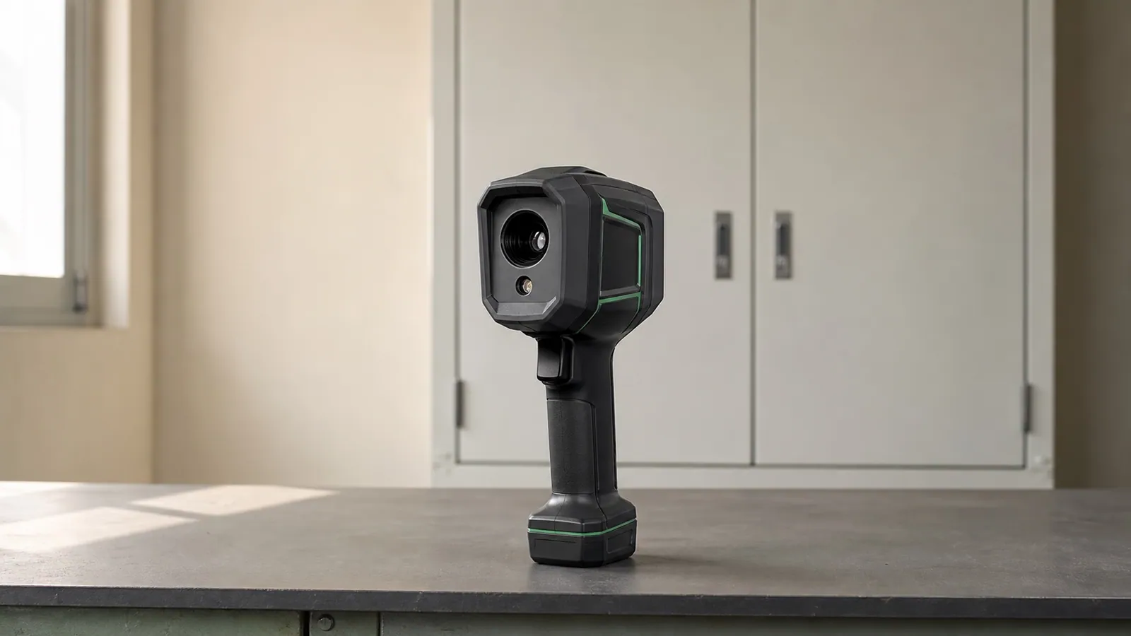
Each detector pixel responds to infrared radiation from the surface in front of it. The camera applies its measurement settings and stores a radiometric image whose pixels can be examined later. The displayed temperature is an apparent surface value; it is shaped by emissivity, reflections, viewing conditions and the camera’s configured parameters.
Provides a spot reading over the instrument’s actual measurement area.
Useful for a defined target; it does not preserve the surrounding thermal field or component geometry.
Stores a temperature-coded image with measurement pixels, regions, palette information and model-dependent visible references.
Useful for locating and comparing patterns across an assembly, then documenting the exact area that deserves follow-up.
ISO 18434-1 covers thermography procedures, interpretation, reflected apparent temperature, emissivity and reporting. ASTM E1934 describes electrical infrared examinations as a way to identify and document exceptions while preserving the need for other knowledge, inspection and tests. ISO 18434-1:2008 · ASTM E1934-99a(2024)
Read the visible reference first so the exact component is clear. The thermal frame then maps apparent surface temperatures onto the palette scale. A crosshair reports one image position; a measurement box can retain the minimum, maximum or average apparent value across a defined region.
Phase 2 shows a warmer apparent pattern than two geometrically similar phase connections. The common materials and side-by-side view make this a useful comparison candidate.
The image alone does not establish load equality, connection condition or root cause. Those questions move into the capture record and qualified follow-up.
The equipment geometry, palette and values in this teaching figure are illustrative. They follow common radiometric-report conventions and do not represent an acceptance limit.
Electrical equipment changes temperature with current, duty, cooling and time. Camera geometry and surface behavior change what reaches the detector. A report keeps these conditions beside the image because they decide whether the comparison can support inspection.
Current and equipment duty influence the heat being produced when the image is captured.
Practical effect: Record the relevant operating state so a warmer pattern can be compared with the work the equipment was carrying.
Different surfaces emit infrared radiation differently. Shiny bare metal can produce unreliable apparent-temperature readings.
Practical effect: Prefer comparisons between similar materials and document the configured emissivity when temperature values influence the finding.
Low-emissivity surfaces can reflect infrared radiation from people, lights or nearby hot equipment into the camera.
Practical effect: A changing reflection may disappear when the viewing geometry changes; a physical anomaly should remain associated with the component.
A blurred or undersized target spreads its thermal signal across neighboring pixels.
Practical effect: Confirm that the component is large enough in the image and sharply focused before relying on a marker or measurement region.
Distance changes how many detector pixels cover the target, while an oblique angle can increase reflections and hide geometry.
Practical effect: Preserve enough detail to identify the asset and keep the capture position repeatable when the image will be compared later.
A thermal camera records infrared radiation from the visible surface. Opaque doors, covers and barriers block the view behind them.
Practical effect: The approved survey method must define which surfaces can be observed safely and which require another access arrangement or test.
Bare reflective metal is a difficult quantitative target. Qualitative comparison between similar equipment under comparable load can provide stronger evidence than an isolated absolute temperature value. Fluke thermography guidance
Thermography becomes more useful when the image can be compared with a peer, a prior record or a post-work condition. The comparison should keep the relevant material, geometry, load and displayed scale aligned closely enough for the difference to mean something.
Three phase connections of the same design, viewed together under similar current.
A phase that departs from its peers can be prioritized while material, geometry and operating context remain closely matched.
One motor starter, feeder or connection recorded under comparable duty on successive surveys.
Trend records show whether an apparent pattern is stable, developing or associated with a changed operating condition.
The same surface, palette range and relevant load context captured before inspection and after a confirmed correction.
The second record verifies whether the observed thermal difference narrowed under a meaningful comparison condition.
Consider a commercial property surveyed while the shared-cooling plant was operating at a stable afternoon duty. The thermographer recorded the feeder identity, three phase currents, visible reference and thermal frame. One phase connection showed a warmer apparent pattern while the measured currents were comparable for this illustrative case.
The phase-to-phase difference was tied to an identified component and persisted after focus, scale and reflection checks. The record justified prioritizing that connection for qualified inspection.
After the equipment was placed under the approved safe-work condition, qualified inspection confirmed deterioration at the termination. That physical finding established the corrective scope. The thermogram had identified the location for inspection.
A post-work image used the same component area, common palette span and comparable operating context. The phase pattern narrowed, giving the owner a direct record of the measured improvement.
The case, temperatures and currents are illustrative. They explain evidence progression and do not create a universal temperature threshold or inspection rule.
The image helps the site choose where to inspect, which operating context to verify and whether a confirmed correction changed the condition. It does not repair the equipment or establish integrity across components that were not visible.
Recorded evidence: One comparable connection or component shows a repeatable apparent-temperature difference.
Decision supported: Direct qualified inspection to the identified asset and preserve the thermogram as the starting evidence.
Recorded evidence: The thermal image is paired with current, duty or operating-state information from the same capture period.
Decision supported: Separate a load-related pattern from one that remains unusual after comparable operating conditions are considered.
Recorded evidence: The anomaly remains tied to a component after reflection, focus and comparison conditions are reviewed.
Decision supported: Select the physical inspection or electrical test that can confirm the remaining hypotheses.
Recorded evidence: A repeat image uses the same asset identification, suitable focus, common scale and comparable load context.
Decision supported: Confirm whether the thermal pattern changed and decide whether further monitoring is still justified.
Recorded evidence: Thermal and visible images remain attached to stable asset names, dates, conditions and interpretations.
Decision supported: Compare future surveys without relying on memory or isolated color impressions.
Detector resolution alone does not define survey quality. The selected camera must resolve the target at the actual distance, focus appropriately, retain radiometric data and support the comparison and report the site expects.
Routine recognition and initial surveys where the target is accessible, sufficiently large in the image and within the camera’s focus behavior.
Selection: Confirm radiometric files, detector resolution, field of view, focus method, visible reference and reporting export.
FLIR C-series and comparable compact radiometric families.
7,000–15,000 MAD
Electrical and mechanical condition surveys requiring clearer thermal detail, robust field use and structured reporting.
Selection: Check measurement tools, thermal sensitivity, focus, image organization, battery provision and included analysis software.
FLIR Ex Pro; Chauvin Arnoux C.A 1954; comparable professional families.
25,000–40,000 MAD
Smaller or more distant targets, demanding electrical surveys, repeatable asset programs and deeper post-capture analysis.
Selection: Confirm spatial resolution at the working distance, lens options, manual level/span, radiometric storage and reporting workflow.
Fluke TiS75+; Testo 883; comparable advanced families.
50,000–85,000+ MAD
Indicative July 2026 MAD equivalents for hardware acquisition. VAT, import, transport, lenses, batteries, software, calibration, training and professional analysis may be excluded. A complete working package can exceed the camera-family band.
Examples identify market families for recognition and scope review. They are not rankings. Features and included accessories vary by exact model. Official references include FLIR E8 Pro, Fluke TiS75+, Testo 883 and Chauvin Arnoux C.A 1954.
A typical electrical survey needs the radiometric camera, suitable focus or lens capability, charged power, storage, visible-reference capture, an asset register and analysis or reporting software. Spare batteries, alternative lenses, remote capture, tripod support and additional software may be package-dependent.
Electrical PPE, controlled access, isolation planning and energized-work controls are site-safety prerequisites. They are not camera accessories, and this article does not provide a live-equipment access procedure.
Name the equipment, operating concern, consequence, surfaces that can be observed and the comparison that will make the image useful.
Qualified personnel establish site controls and record the relevant load, duty, environmental condition and access limitation.
Confirm suitable camera capability, charged batteries, lens or focus behavior, storage, visible-image capture, asset register and reporting software.
Identify the exact component, obtain a sharp thermal and visible pair, check palette level/span and preserve the relevant configured parameters.
Compare equivalent components or prior records, state confidence, list unresolved causes and identify the qualified inspection or test required next.
After confirmed work, repeat the image under a comparable condition and retain both records with the action taken and remaining limitation.
The first review should establish whether a repeatable pattern is tied to an identified component, whether the operating and surface conditions support comparison, and which uncertainty requires inspection or another test. It should also state when a different viewpoint, higher-detail camera, repeat operating condition or additional measurement is needed.
A screenshot without its radiometric file and capture record is difficult to revisit. The handover should preserve enough information for another qualified reader to understand the observation, its confidence and the verification path.
Thermography report record
Before commissioning
Thermography personnel competence materially affects capture and interpretation. ISO 18436-7:2014 specifies qualification and assessment requirements for personnel performing machinery condition monitoring with infrared thermography.
These answers clarify substitution, image interpretation, access and scope without replacing the survey method selected for the site.
Electrical thermography makes surface-temperature differences visible across identified equipment. A well-documented survey can prioritize inspection, narrow the next test, support corrective planning and verify whether a confirmed repair changed the measured pattern.
Locate an apparent thermal exception at a named component.
Judge the pattern against load, surface behavior and a useful comparison.
Direct qualified inspection or testing toward the remaining uncertainty.
Repeat the capture under comparable conditions after confirmed work.
Retain a visible, radiometric and interpretive record for future comparison.
The survey remains a snapshot of visible surfaces at the recorded operating condition. Root cause, hidden-component condition and future equipment reliability require qualified follow-up beyond the thermogram.
Send the image, asset context, operating condition or proposed scope. ReneWave can explain what the thermal record supports, what remains unresolved and which follow-up should be specified.
 RENEWAVE
Energy systems, held to standard.