Galvanized cable trays and accessories datasheetdatasheet · Morocco · French2023-02-08 · product family
IngelecBest Value
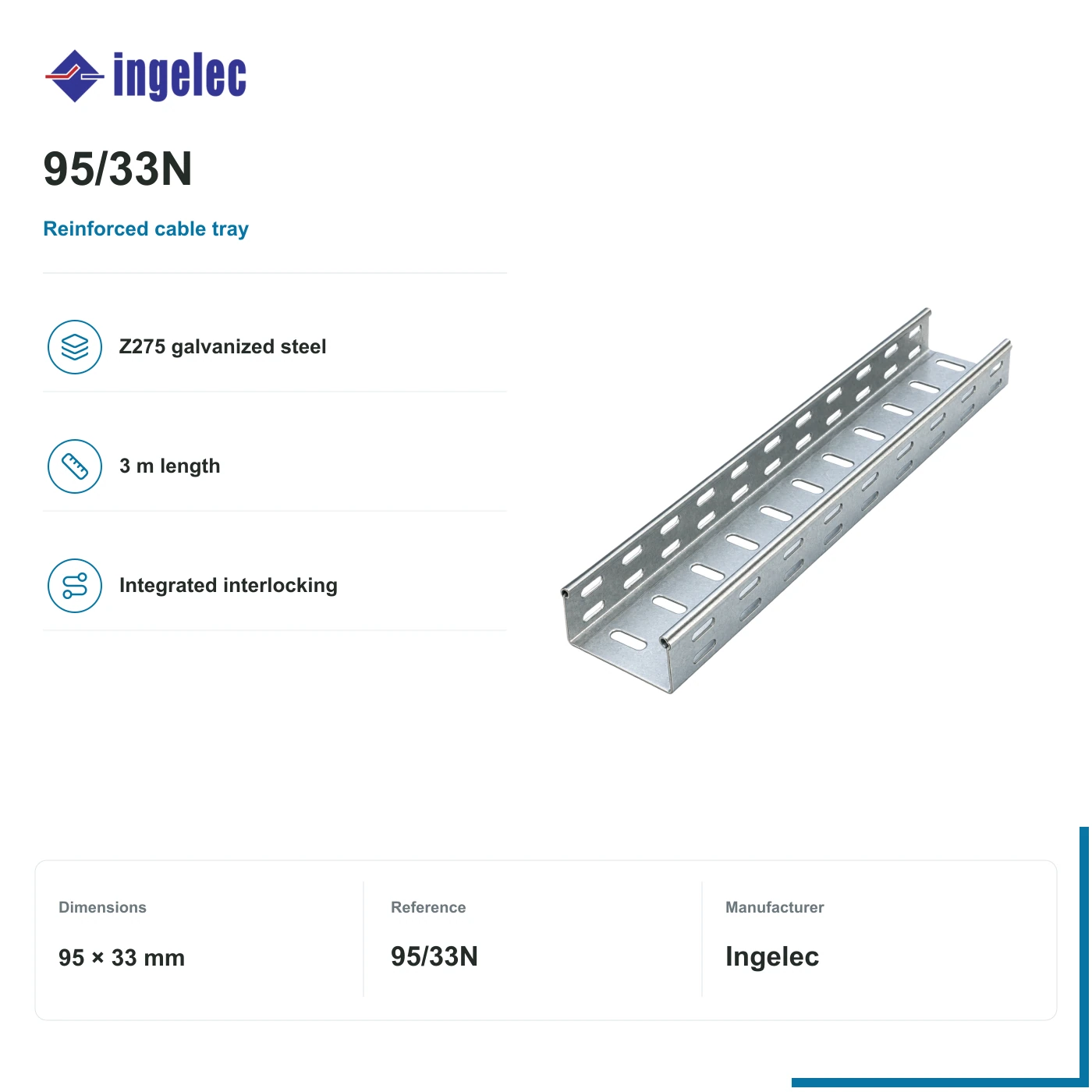
Ingelec reinforced galvanized cable tray · 95 × 33 mm
Exact reference · 95/33N
Reinforced perforated steel tray, 95 × 33 mm (width × side height), in 3 m lengths. Galvanized Z275; supports and cover are separate.
- Profile · width × height
- 95 × 33 mm
- Length per item
- 3 m
- Material
- Z275 · EN 10327-DX51D
- Steel thickness
- 0.5 mm
This accessory does not set the electrical protection rating of a complete installation. The equipment, wiring and assembly are selected for the project.
Pricing confirmed by quote
The written quote confirms the exact reference, required accessories, compatibility, delivery and commercial terms.
Availability confirmed in your written quote
1
01 · Product role
What this product does in the system.
Reinforced perforated trays carry sheathed cables along a separately designed support route. These galvanized profiles have integrated interlocking ends and 25 × 7 mm slots. Load capacity depends on the exact reference, support spacing and assembly conditions.
Relevant applications
- Supporting sheathed cables on a designed wall-mounted or suspended route.
Why ReneWave may shortlist it
- Reinforced Z275 galvanized steel profile.
- Integrated interlocking ends and perforated base.
Where it fits in the installation
Perforated cable tray95/33N
Solar installation example
Solar panels
PV array
Solar inverter
DC to AC conversion
AC protection & control
Equipment selected for the project
Cable route
Conductors between equipment
Selected item here · 95/33N
Site equipment
Equipment supplied by the installation
Example AC-side placement; protection and wiring are selected for the project.
Arrows show the connection order of the example equipment. The highlighted accessory houses, mounts or supports it; it does not conduct the working current.
How the item is used
Between the electrical assembly and site equipment, the tray supports the cable run. Cables and mounting supports are selected separately.
Perforated cable tray
Cables · separate
Selected item
Perforated cable tray
Read the technical explanation
Reinforced perforated steel tray, 95 × 33 mm (width × side height), in 3 m lengths. Galvanized Z275; supports and cover are separate.
02 · Specifications
Ratings, dimensions and practical consequence.
Construction and mechanical fit
- Manufacturer reference
95/33N
- Profile · width × height
95 × 33 mm
- Length per item
3 m
- Material
Z275 · EN 10327-DX51D
- Steel thickness
0.5 mm
- Slots
25 × 7 mm
- Joint arrangement
Integrated interlocking ends
- Load reference
Exact N reference and support span · datasheet p. 8
03 · Confirm before quotation
Four checks before this reference is quoted.
Confirm physical dimensions, cable routing, installation conditions and the exact supplied parts before quotation.
- 01

Dimensions and mounting
Choose both width and side height for cable fill, cable mass and reserved space.
- 02

Cable route
Use the manufacturer load table for this reference and the actual support span. Supports, bends, joints and fixings are separate.
- 03

Installation environment
Check corrosion exposure, edge protection and electrical continuity/bonding for the complete installed route.
- 04

Exact reference and supply
Confirm the reinforced N reference, 3 m supply length and any cover. Do not substitute a standard or painted reference.
04 · Documentation
Keep the exact reference traceable.
Published documents for this exact reference support selection and handover.
Industry catalogueguide · Morocco · French2022 catalogue · product family
05 · Complete the system
Accessories and adjacent equipment, in one request.
Select relevant companions now. ReneWave still verifies quantities and compatibility before they appear in the written quote.
No additional equipment is published for this reference. Required accessories are confirmed during quotation.
1
