Maintenance Technology Atlas
    Technology article · Protection and fault finding

    Cable Fault Locators and Time-Domain Reflectometry: What Reflection Traces Can Reveal

    A time-domain reflectometer sends a controlled low-voltage pulse into a metallic cable and records reflections from changes in impedance. The instrument converts the return time into an estimated electrical distance using the selected propagation setting.

    TDR provides pre-location evidence. Cable schedules, route geometry, joints and any specialist pinpointing still determine where qualified inspection or repair should begin. The baseline described here uses an identified, isolated and discharged cable.

    Reflection traceElectrical distanceCable route
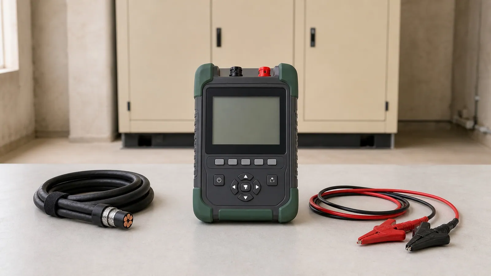
    Compact professional time-domain reflectometer with protected input ports, test leads and a power-cable sample
    Recognition view: a compact TDR, lead set and cable sample used to preserve a reflection trace and estimated electrical distance.
    01 · From pulse to estimated distance

    A returned pulse marks a change along the cable.

    The pulse travels away from the test end. A joint, cable transition, open end, short circuit or fault can change the cable impedance and return part of the signal. The TDR records the interval between transmission and return.

    The figure shows the evidence relationship. It omits terminals, cable preparation and connection instructions.

    PULSE · REFLECTION · DISTANCEConceptual evidence path · no connection procedureTDROUTGOING PULSEtravels along the named cableIMPEDANCE CHANGEJOINTor faultRETURNED REFLECTIONIts direction and shape depend on the impedance change.Known joints can reflect without being faults.THE DISPLAYED DISTANCETEST ENDREFLECTIONReturn time + propagation settingbecomes estimated electrical distance.Illustrative model · not a physical route or excavation point

    Time-domain reflectometer

    Produces a reflection trace and estimated distance along a suitable metallic cable. Basic TDR is strongest when the fault creates a visible impedance change.

    Cable route locator

    Traces the physical cable route through its supported method. It can help place the TDR distance on the site but does not produce the same reflection record.

    Insulation resistance tester

    Characterizes resistance across a named insulation path. It can support fault characterization but normally does not estimate distance along the cable.

    IEEE 1234-2019 describes fault-location techniques for shielded power cable systems and their limitations. BAUR's TDR method reference explains low-voltage pulse reflection, cable-end, joint and low-resistance fault behavior.

    02 · Reading a reflection trace

    The trace preserves where the affected cable stops matching its reference.

    Read from left to right. The horizontal axis shows estimated electrical distance in metres after the propagation setting is applied. The vertical movement shows relative reflection amplitude. It describes the direction and strength of an impedance change rather than a universal severity scale.

    The green reference and red affected trace share the same illustrative cable and settings. The cursor marks their repeatable divergence at about 78 metres.

    TDR REFLECTION RECORDIllustrative metallic power-cable traceRELATIVE REFLECTION AMPLITUDESOURCEKNOWN JOINTDIVERGENCE · 78 mCABLE ENDESTIMATED ELECTRICAL DISTANCE →Reference core or stored traceAffected cable traceCursor or known route featureValues use an illustrative propagation setting.Relative amplitude has no universal pass/fail threshold.

    Source pulse

    The first large response belongs to the launch area and establishes the start of the distance record.

    Known joint

    A documented impedance transition can create a repeatable feature without being the present fault.

    Trace divergence

    The affected and reference traces separate at a cursor selected by the qualified reader.

    Cable end

    The final reflection helps confirm the represented cable length and whether the earlier event occurs before it.

    The figure follows graphical trace, cursor, distance and comparison conventions documented for Megger TDR2050 and Sonel TDR-420. Its traces and values are illustrative.

    03 · What changes the estimate

    The same return time can produce a different displayed distance.

    The TDR calculation needs a propagation velocity that represents the cable. Settings also influence whether reflections remain separated and recognizable. The report should retain them with the raw trace so another qualified reader can reconstruct the estimate.

    01

    Propagation setting

    The instrument converts pulse return time into distance using the selected propagation velocity or velocity factor.

    A setting that does not represent the cable changes every displayed distance, even when the underlying return time stays the same.

    02

    Cable construction and sections

    Conductor arrangement, insulation system and characteristic impedance influence how the pulse travels and reflects.

    Mixed cable sections can require separate assumptions, measurements from both ends or a wider physical search zone.

    03

    Pulse width, gain and range

    Short pulses can separate nearby features, while longer ranges and additional gain help retain distant reflections through attenuation.

    Poor settings can hide a nearby event in the launch zone, merge separate events or amplify noise into an uncertain trace.

    04

    Joints, branches and cable ends

    A joint, tee, transition, open end or short circuit can each change impedance and create a reflection.

    Known route features must be marked before an unfamiliar trace change is treated as the fault.

    05

    Fault condition

    Basic low-voltage TDR traces commonly reveal opens, shorts and sufficiently low-resistance impedance changes.

    High-resistance, intermittent or breakdown faults may require a specialist reflection, surge, acoustic or electromagnetic method.

    06

    Reference evidence

    A commissioning trace, healthy core, opposite-end measurement or reliable cable schedule gives the new trace a comparison basis.

    Comparison can separate an existing joint or cable transition from the feature introduced by the present fault.

    04 · From electrical distance to repair zone

    The cable route gives the cursor a physical context.

    Electrical distance follows the cable conductor. Site drawings, known joints, bends, risers, service loops and accessible ends translate that distance into a physical search zone. Mixed cable sections can widen the uncertainty because propagation velocity changes between sections.

    Route tracing, measurements from the opposite end, acoustic or electromagnetic pinpointing and controlled sectional checks may be required before physical access begins.

    FROM ELECTRICAL DISTANCE TO INSPECTION ZONEConceptual site record · no excavation instructionMAIN LV ROOMTDR test endJ1RISER+ slack78 m CURSORINSPECTION ZONEafter route reconciliationREMOTE ANNEXTHE ROUTE RECORD ADDSKnown joint and cable-section changesBends, risers, slack and accessible endsRoute tracing or opposite-end evidenceQualified physical pinpointing where requiredThe cursor narrows the search; it is not a map coordinate.

    Electrical marker

    The cursor identifies distance from the stated test end under the recorded propagation basis.

    Route evidence

    Drawings and site tracing account for the actual path rather than straight-line surface distance.

    Inspection zone

    Qualified confirmation narrows where access or repair is justified and records the remaining uncertainty.

    05 · Commercial-property example

    A feeder fault after drainage work required a targeted inspection zone.

    A buried low-voltage feeder supplies a remote loading and packaging annex. Protection operates after civil work crosses part of the documented route. The owner needs the fault located without opening the entire route.

    01

    Operating event

    Protection operates on the buried LV feeder serving a remote loading and packaging annex after drainage work crosses the recorded route.

    The event identifies the affected feeder and business consequence. It does not establish the cable section or physical damage.

    02

    Fault characterization

    Qualified checks confirm a low-resistance fault condition on the isolated feeder and establish which cores can provide affected and reference traces.

    The fault condition supports low-voltage TDR pre-location under the approved method.

    03

    Electrical pre-location

    The affected trace diverges from the healthy reference at an illustrative electrical distance of about 78 metres from the test end.

    The marker narrows the cable distance. Propagation assumptions, cable sections and route geometry still affect its physical interpretation.

    04

    Route reconciliation

    The cable schedule, known joint, riser allowance and physical route place the estimate near the recent service crossing. Qualified route tracing and pinpointing define the inspection zone.

    The combined evidence justifies a targeted opening instead of treating the TDR cursor as an excavation coordinate.

    05

    Repair and verification

    Inspection confirms mechanical cable damage. After repair and restoration, the team retains a comparable TDR trace and completes the required insulation, continuity and protection checks.

    The records show that the reflected feature changed and that the repaired feeder received the wider verification required before return to service.

    The scenario, trace and 78-metre marker are illustrative. The actual cable construction, fault condition, route, protection and approved methods govern the investigation.

    06 · What the evidence can change

    A credible trace reduces the route that needs physical investigation.

    The record can distinguish an early cable end, repeatable low-impedance change, known joint or inconclusive fault condition. Each pattern changes the next method, access plan and verification record.

    01

    Recorded evidenceA strong positive reflection appears before the documented cable end.

    Investigation or actionReview an open circuit, cable break, disconnected end or another high-impedance transition near the estimated distance.

    VerificationConfirm the physical condition and retain the post-work trace against the same cable identity and propagation basis.

    02

    Recorded evidenceThe affected trace moves sharply away from a healthy reference at one repeatable position.

    Investigation or actionReconcile the electrical distance with joints, route records and access points, then select the required physical pinpointing method.

    VerificationRepeat the trace from the same test end or compare from the opposite end where the route and method support it.

    03

    Recorded evidenceA repeatable trace change aligns with a known joint or cable transition.

    Investigation or actionKeep the known feature in the route model and assess whether its present shape differs from commissioning or healthy-phase evidence.

    VerificationPreserve the reference and affected traces so later work can show whether the feature changed.

    04

    Recorded evidenceThe operational fault is credible but the basic TDR trace remains inconclusive.

    Investigation or actionEscalate to a specialist method suited to a high-resistance, intermittent or breakdown fault instead of forcing a distance from weak evidence.

    VerificationRetain the method that activated or localized the condition and the physical confirmation that followed.

    05

    Recorded evidenceThe post-repair trace no longer contains the previous divergence under comparable settings.

    Investigation or actionUse the comparison as one part of the restoration record.

    VerificationComplete the applicable insulation, continuity, protection, identification and functional checks before handover.

    07 · Choosing equipment

    Fault behavior and confirmation needs determine the equipment family.

    A handheld TDR can answer many routine pre-location questions. Two-channel instruments improve comparison and retained evidence. Integrated systems add specialist methods for faults that a basic low-voltage pulse does not reveal clearly.

    Handheld metallic-cable TDR

    Routine cable length, open, short and impedance-change pre-location on suitable power, control and other metallic cable pairs.

    Selection: Confirm input protection, cable range, propagation setting, impedance choices, pulse control, cursor behavior, trace hold and included lead set.

    Sonel TDR-420; Megger TDR1000/3P.

    12,000–25,000 MAD

    Advanced dual-channel power TDR

    Power-cable work requiring affected/reference comparison, stored traces, stronger input protection and finer control of difficult records.

    Selection: Confirm two-channel operation, fused leads, trace memory, distance-dependent gain, near-end performance, export and complete accessories.

    Megger TDR2050 and comparable advanced power TDR families.

    50,000–80,000+ MAD

    Integrated pre-location and pinpointing system

    Specialist LV or MV cable-fault work where high-resistance or breakdown faults require additional reflection, surge, route or pinpointing methods.

    Selection: Define cable class, fault characterization, supported pre-location methods, route locator, acoustic/electromagnetic receiver, safety controls, software and training.

    Megger EZ-THUMP; BAUR IRG 4000, Syscompact and related systems.

    Project-priced

    Indicative July 2026 MAD equivalents for hardware acquisition, using approximately 1 EUR = 10.7 MAD. VAT, import, transport, adapters, fused leads, blocking filters, couplers, route locators, acoustic receivers, surge equipment, software, calibration, training and professional services may be excluded. Integrated systems are project-priced because configuration changes the scope materially.

    Examples support recognition and proposal review; they are not rankings. Official references include Megger TDR2050, Sonel TDR-420, Megger EZ-THUMP and BAUR IRG 4000.

    08 · Complete kit and qualified process

    The TDR body supplies one part of the fault-location record.

    A practical baseline includes the instrument, compatible protected leads and adapters, reliable power, memory or export, cable data, route records, current documentation and calibration status. Route locators, cable-identification equipment, blocking filters, couplers, opposite-end access, acoustic receivers and integrated reflection or surge systems remain package- and method-dependent.

    Cable identification, isolation, discharge, connection, high-energy methods, excavation, repair and restoration remain qualified responsibilities under the approved site and manufacturer methods.

    01

    Characterize and prepare

    Named cable, cores, operating symptom, protection event, cable schedule, route drawing, known joints, accessible ends, isolation and discharge responsibility.

    02

    Pre-locate and validate

    TDR, rated or fused leads, cable range, propagation basis, impedance, pulse, gain, cursors, affected/reference traces and an uncertainty statement.

    03

    Reconcile and pinpoint

    Electrical distance, route length, bends, slack, risers, joints, opposite-end evidence and any qualified route, acoustic or electromagnetic pinpointing.

    04

    Repair, restore and verify

    Confirmed physical condition, repair boundary, comparable post-work trace, cable identification, insulation, continuity, protection and restoration evidence.

    First useful analysis

    The trace must narrow a justified next action.

    The first review identifies whether a repeatable reflection appears before the cable end, which reference supports it, how propagation and route assumptions affect the distance, and whether basic TDR is sufficient. The output should recommend route reconciliation, another measurement point, specialist pinpointing or another fault-location method without inventing certainty.

    09 · Report and review

    The report separates trace distance from the confirmed physical location.

    A screenshot containing one cursor cannot reconstruct the cable, settings, route or uncertainty. The retained record connects the raw trace to the exact cable and shows how the repair zone was confirmed.

    Cable identity
    Site, feeder or control-cable reference, cores represented, conductor and insulation information, route drawing and known joints or transitions.
    Controlled state
    Isolation reference, cable identification, far-end condition, discharge confirmation, connected-equipment controls and responsible qualified personnel.
    Instrument and settings
    TDR, serial and calibration status, channel, propagation factor, impedance, range, pulse width, gain, cursor positions and software version where relevant.
    Trace evidence
    Raw affected and reference traces, test end, timestamp, cable-end marker, known features, divergence and displayed electrical distance.
    Route interpretation
    Physical route, slack and bends, joints, mixed sections, distance uncertainty, opposite-end evidence and selected inspection or pinpointing zone.
    Confirmation and restoration
    Physical condition found, repair completed, post-work trace, additional cable tests, protection checks, restoration and remaining limitations.
    Practical FAQ

    Questions that often remain after a cable fault-location proposal.

    These answers clarify distance, neighboring instruments, difficult faults, safety state and post-repair evidence.

    No. The displayed value is an estimated electrical distance along the cable under the selected propagation setting. The physical route can include bends, slack, risers, joints and mixed cable sections, so route reconciliation and qualified pinpointing define the inspection zone.

    A route locator identifies the physical path and depth behavior supported by its method. A TDR records reflections and estimates distance along the metallic cable. Many investigations use both because route and electrical-distance evidence answer different parts of the location problem.

    An insulation resistance tester can characterize resistance across a named insulation path under its approved method. It normally does not provide distance along the cable. The result can help characterize the condition while TDR or another location method addresses position.

    A high-resistance, intermittent or breakdown fault may not create a clear impedance change under the TDR low-voltage pulse. Cable attenuation, settings, branches and the near-end blind zone can also weaken the record. Specialist reflection, surge, acoustic or electromagnetic methods may be required.

    The safe baseline for this article is an identified, isolated and discharged cable tested under a qualified method. Some exact instruments support protected measurements in limited energized conditions, but that capability, lead set, installation category and procedure must be verified specifically and is not assumed here.

    The comparison can show that the previous reflected feature changed under comparable settings. It cannot establish every insulation, conductor, joint, protection or installation condition. The restoration record also needs the other tests and inspections applicable to the repaired cable.
    Conclusion

    What credible cable pre-location makes possible.

    A TDR can estimate where a reflected cable feature lies from the stated test end, compare an affected trace with useful reference evidence and reduce the route that requires physical investigation.

    01

    Preserve the cable, test end and settings.

    02

    Separate known joints from new trace changes.

    03

    Translate electrical distance through the physical route.

    04

    Use specialist pinpointing when the fault requires it.

    05

    Verify the repaired cable with comparable and complementary records.

    The trace cannot identify every fault type, physical cause, exact surface position or complete cable condition automatically. Its practical value comes from controlled evidence, a defensible propagation basis, route reconciliation, qualified confirmation and a documented post-repair comparison.

    Cable fault evidence

    Have a cable fault trace or location proposal to review?

    Send the fault symptom, cable schedule, route drawing, protection event, existing trace or proposed method. ReneWave can explain what the distance marker represents, which assumptions affect it and what evidence should remain after repair.

    ReneWave markRENEWAVE

    Energy systems, held to standard.