Manufacturer datasheetdatasheet · France: technical record; not commercial terms · French
Schneider ElectricPremium
Schneider GV3P401 · motor breaker
Exact reference · GV3P401
TeSys GV3P GV3P401: 3 protected poles, thermal adjustment 30–40 A. Thermal overload and magnetic short-circuit protection.
- Rated current / adjustment
- 30–40 A
- Magnetic trip threshold
- 560 A
- Icu · IEC/EN 60947-2
- 50 kA · 400/415 V AC · 50/60 Hz
Protects against overload and short circuit. No integrated residual-current protection. Choose conductors, fault capacity and upstream/downstream coordination for the installation.
Pricing confirmed by quote
Quote confirms reference and commercial terms; installation selection remains the installer’s responsibility.
Availability confirmed in your written quote
1
01 · Product role
What this product does in the system.
TeSys GV3P GV3P401: 3 protected poles, thermal adjustment 30–40 A. Thermal overload and magnetic short-circuit protection.
Relevant applications
- Motor switching or protection in a separately coordinated equipment circuit.
Why ReneWave may shortlist it
- TeSys GV3P GV3P401: 3 protected poles, thermal adjustment 30–40 A. Thermal overload and magnetic short-circuit protection.
System position
AC protection: conceptual single-line view.
Protects against overload and short circuit. No integrated residual-current protection. Choose conductors, fault capacity and upstream/downstream coordination for the installation.
Supply reaches the selected circuit through the closed breaker. PE remains connected outside the device.
Read the technical explanation
Protects against overload and short circuit. No integrated residual-current protection. Choose conductors, fault capacity and upstream/downstream coordination for the installation.
02 · Specifications
Ratings, dimensions and practical consequence.
Device identity
- Schneider reference
GV3P401
- Protection function
Motor circuit breaker
- Pole arrangement
3P
Electrical ratings
- Rated current / adjustment
30–40 A
- Magnetic trip threshold
560 A
- Icu · IEC/EN 60947-2
50 kA · 400/415 V AC · 50/60 Hz
- Ics · IEC/EN 60947-2
100% × Icu · 400/415 V AC · 50/60 Hz
Mounting and connections
- Mounting and connections
EverLink BTR, one terminal block. Keep the final 1 suffix; do not substitute the two-block reference.
- Installation boundary
Mounting and conductor preparation follow the exact manufacturer drawing and terminal table; no accessories are assumed included.
03 · Selection points
Four practical selection points.
Select by the circuit duty and exact manufacturer reference.
- 01
Pole arrangement
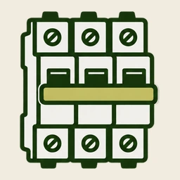
3 switched and protected poles. PE remains outside the switching path. Assign any neutral conductor only according to the installation design.
- 02
Current and protection function
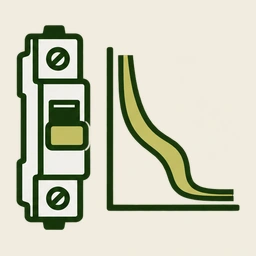
Match the thermal adjustment to the motor nameplate current and operating duty, not a C-curve distribution rating.
- 03

Voltage and fault capacity
Icn, Icu and Ics are different ratings. Values below are qualified by voltage, frequency and standard; other voltages follow the datasheet.
- 04
Mounting and connections
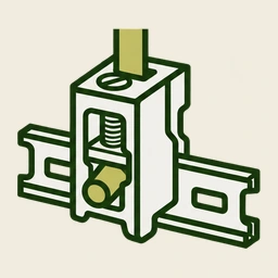
EverLink BTR, one terminal block. Keep the final 1 suffix; do not substitute the two-block reference.
04 · Documentation
Keep the exact reference traceable.
Published documents for this exact reference support selection and handover.
05 · Complete the system
Accessories and adjacent equipment, in one request.
Separate equipment is selected for the installation; no automatic companions are added to your request.
No automatic companion selection. Separate protection and accessories are chosen for the installation.
1
