Maintenance Technology Atlas
    Technology article · Protection and fault finding

    Protection-System Testing: What Injection and Trip Records Can Reveal

    A protection test set applies controlled current, voltage, phase, frequency or digital conditions to a protection relay. It records when the relay picks up, how long it takes to operate, which logic or output changes state, and whether those results match the approved settings for the tested function.

    Each result belongs to a declared boundary. A relay-level test can establish relay behavior. Evidence for sensors, communications, auxiliary trip wiring and breaker action requires those elements to be included through the appropriate qualified test scope.

    Secondary injectionRelay timingTrip-path evidence
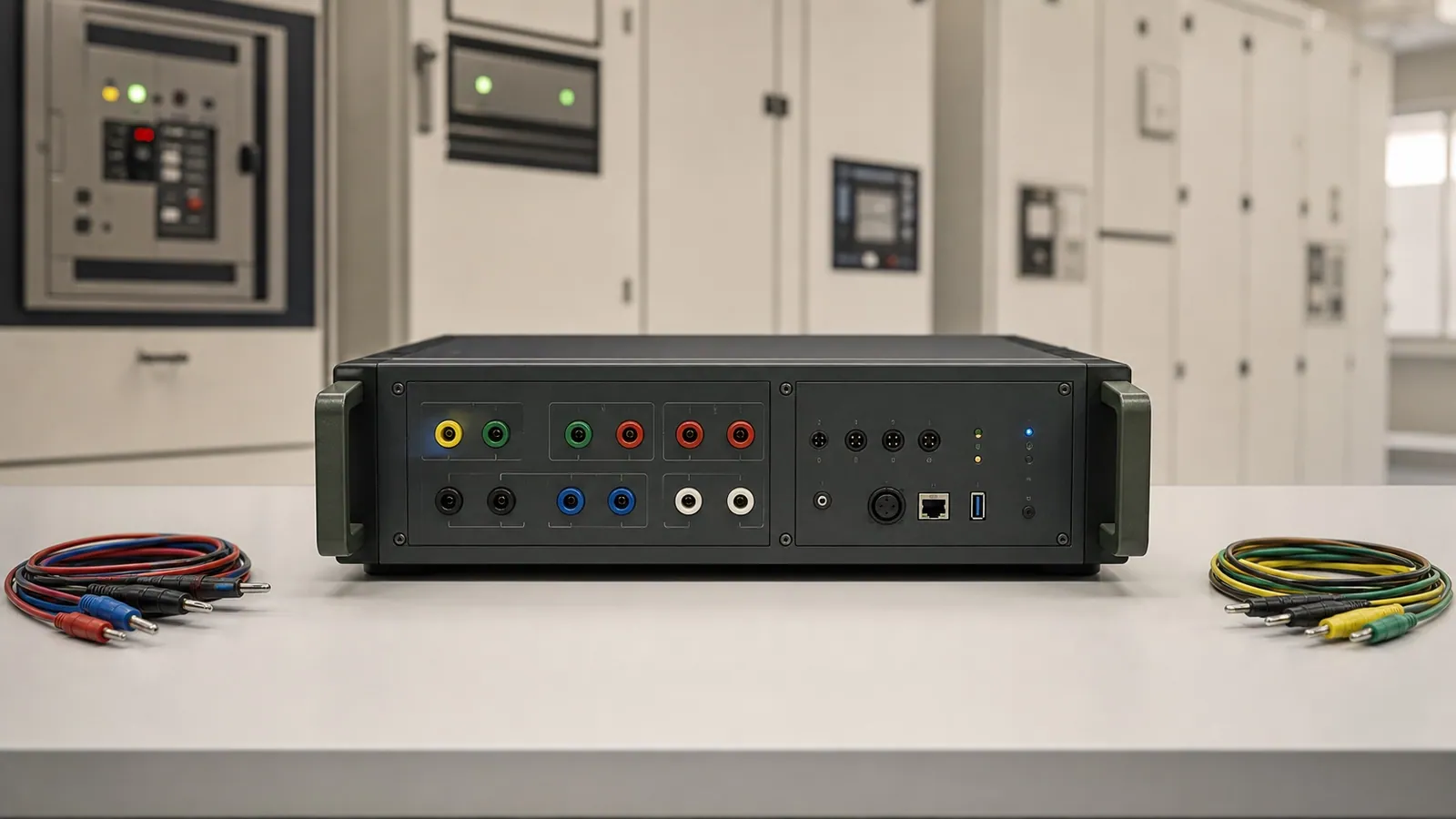
    Brand-neutral multiphase protection test set with current and voltage outputs, binary inputs and orderly protected leads beside closed relay panels
    Recognition view: a multiphase relay test platform, separate channel groups and protected lead sets prepared beside closed protection panels.
    01 · The protection boundary

    Protection operates through a chain of separate functions.

    Current and voltage sensors represent the electrical system at relay inputs. The relay evaluates those quantities through approved settings and logic. A trip output then depends on auxiliary supply, field wiring, intermediate devices and breaker controls before the breaker can change state.

    The green area shows the typical relay-level secondary-injection boundary. The dashed red area identifies the additional evidence required when the declared functional path extends to breaker action.

    PROTECTION CHAIN AND TEST BOUNDARIESConceptual system roles · no test connection procedureRelay-level recordWider trip-path recordCT / VT SENSORSscaled system quantitiesRELAY MEASUREMENTcurrent · voltage · phasePROTECTION LOGICapproved settings and logicRELAY OUTPUTtrip or alarm stateAUXILIARY TRIP PATHsupply · wiring · devicesBREAKERdeclared state changeA pass applies only to the elements included in the declared boundary.

    Relay measurement and logic

    Secondary injection can establish how the selected relay function responds to a controlled input.

    Output and auxiliary path

    A declared functional test adds the output assignment, auxiliary supply and trip wiring represented by the scope.

    Breaker state

    Breaker operation is separate evidence and must be planned, authorized and recorded when it forms part of the test.

    IEEE C37.233-2023 addresses testing of protection components and complete protection and control schemes, including their declared boundaries.

    02 · Reading a test report

    Every measured point is compared with an approved expectation.

    The example below uses an inverse-time overcurrent function. The horizontal axis expresses injected current as a multiple of the approved pickup setting. The vertical axis records relay operating time. The green curve and pale band represent the setting-specific expected response and its approved tolerance; the red points are measured results.

    The shape is a recognizable teaching example for an inverse-time function. Other functions produce different test records. Every value shown here is illustrative.

    SETTING-SPECIFIC OVERCURRENT TESTIllustrative values · approved setting defines expectationOPERATING TIME (seconds)01234APPROVED PICKUP1x2x3x4x5xINJECTED CURRENT / APPROVED PICKUP →ILLUSTRATIVE RESULT ROWTEST POINT3.0 x approved pickupEXPECTED BAND0.55-0.70 sMEASURED0.62 s · output operatedRESULTInside approved expectationNo value shown is a universal pickup or timing requirement.

    Pickup

    The input level at which the tested relay element begins to assert under the approved method.

    Operating time

    The measured interval between the defined applied condition and the declared relay response.

    Expected band

    The permitted range derived from approved settings, relay behavior, the test plan and its stated tolerance source.

    Measured result

    The applied quantity, observed time and output state retained for the exact point.

    IEC 60255-151:2009 provides functional requirements for overcurrent and undercurrent protection. IEC 60255-1:2022 provides common requirements and reference conditions for measuring relays and protection equipment.

    03 · Selecting the test scope

    The required finding determines how much of the scheme must be tested.

    Relay behavior, sensor transformation, trip-path operation and coordinated scheme behavior are different findings. A proposal should name the question and include the elements needed to answer it.

    01

    Relay secondary injection

    Controlled current and voltage quantities are applied at the relay-level test boundary. Pickup, operating time, logic and declared outputs can be recorded.

    This scope verifies the selected relay behavior against approved setting-specific expectations. Primary sensors, field wiring and breaker mechanics remain outside unless separately included.

    02

    Primary injection

    A suitable primary-current method includes declared current-transformer ratios, polarity, wiring and relay response within the planned test boundary.

    It can verify more of the measurement chain. The exact equipment, outage, current level and protection arrangements require a separate qualified method.

    03

    Functional trip-path test

    The relay output, auxiliary supply, trip wiring and selected breaker operation are exercised through a declared functional path.

    This scope answers whether the tested command reaches the breaker and produces the expected state change. It must record blocked functions and restoration.

    04

    Synchronized or digital end-to-end test

    Coordinated test sets or supported digital interfaces reproduce conditions at multiple scheme locations with a common time reference.

    This scope is used when communications, directional comparison, line differential or IEC 61850 applications must operate as one scheme.

    IEC TR 61850-10-3:2022 addresses functional testing of IEC 61850 substation applications. Exact digital, communication and synchronization capabilities remain platform- and scheme-specific.

    04 · Test identity

    A result is valid only for the settings, function and boundary recorded with it.

    A bare pass label cannot show which settings group was active, which output was observed or which equipment remained outside the test. The identity record allows another qualified reader to reconstruct the result and repeat it after a correction.

    01

    Protected asset and function

    Feeder, transformer, motor, bus or line; relay identifier; tested element; declared trip or alarm path; and the operating decision the test supports.

    02

    Approved settings

    Controlled settings revision, active settings group, protection study reference and the expected pickup, timing, logic or communication behavior for each point.

    03

    Measurement basis

    CT and VT ratios, nominal frequency, phase convention, relay input basis and any scaling used to translate injected quantities into the report.

    04

    Relay and test platform

    Relay model, firmware, enabled functions, test-set identity, software version, channel configuration, calibration status and time synchronization where required.

    05

    Test state

    Auxiliary supply, breaker state, communications state, temporarily blocked functions, substitute protection and every element included or excluded from the boundary.

    06

    As-left control

    Corrections, repeated points, final settings checksum or export, restored blocks, restored trip path, returned equipment state and accountable handover.

    05 · Manufacturing-site example

    The relay passed while the breaker remained closed.

    A feeder relay is replaced in a manufacturing site's private medium-voltage substation. Secondary injection is planned first, followed by the wider functional trip path required for handover. The two records answer different questions.

    01

    Replacement scope

    A manufacturing site replaces one feeder relay in its private MV substation. The approved settings file, CT and VT basis, output allocation and planned test boundary are controlled before work begins.

    The owner needs evidence for the new relay behavior and for the declared breaker trip path before the feeder returns to service.

    02

    Relay-level result

    Secondary injection records pickup and operating time within the approved setting-specific expectation. The relay output assigned to the trip function also changes state.

    The selected relay function passes inside the relay-level boundary. Breaker operation has not yet been established.

    03

    Wider functional result

    During the planned functional test, the relay output operates and the breaker remains closed. Auxiliary supply is present and the event timestamps remain aligned.

    The additional record places the unresolved condition between the relay output assignment and the breaker action represented by the wider boundary.

    04

    Physical confirmation

    Qualified inspection finds that the replacement relay maps the trip function to the wrong physical output. The approved output mapping is restored under settings control.

    The inspection establishes the configuration error responsible for the failed functional path. The earlier relay timing result remains valid for its narrower boundary.

    05

    As-left verification

    The same relay test points and functional trip record are repeated. Pickup and timing remain within expectation, the declared relay output operates, and the breaker changes state as planned.

    The report retains both boundaries, the correction, repeated evidence, restored blocked functions and the final settings revision.

    The scenario and test values are illustrative. Actual settings, tolerances, protection arrangements, outage controls and return-to-service authority come from the approved project and site records.

    06 · What the evidence can change

    Boundary-aware results direct the next inspection or correction.

    The report should connect each deviation to the smallest credible investigation boundary, then preserve the repeated point that verifies the confirmed correction.

    01

    Recorded evidencePickup or operating time falls outside the approved setting-specific expectation.

    Investigation or actionReview the active settings group, calculation basis, relay condition, test configuration and approved tolerance source before return to service.

    VerificationRepeat the affected points after the confirmed correction and retain the original and as-left records.

    02

    Recorded evidenceRelay input and logic behave correctly while the declared output does not change state.

    Investigation or actionExamine output logic, enabled functions, mapping and the relay output stage within the qualified test boundary.

    VerificationRepeat the same applied condition and retain the output-state record after correction.

    03

    Recorded evidenceThe relay output operates while the breaker remains closed during a wider functional test.

    Investigation or actionInspect the auxiliary trip path, interposing devices, wiring, breaker control and declared temporary blocks under the approved method.

    VerificationRepeat the functional path and preserve relay output, trip-circuit and breaker-state evidence on one time basis.

    04

    Recorded evidenceTwo remote relay elements pass individually but the coordinated scheme fails.

    Investigation or actionReview communications, time synchronization, logic exchange and end-to-end test conditions across the complete declared scheme.

    VerificationRepeat the synchronized scenario and retain records from both ends with a common clock.

    05

    Recorded evidenceAll selected test points pass and every temporary block is restored.

    Investigation or actionUse the report as one part of the qualified return-to-service decision for the exact tested boundary.

    VerificationRetain as-left settings, test results, restoration checks and every excluded element that still requires separate evidence.

    07 · Choosing equipment

    Functions, channels and scheme complexity shape the platform.

    A focused instrument can serve many routine protection checks. Three-phase, differential, communications-assisted and digital schemes require more sources, binary channels, timing, automation and software. Package contents and licensed functions vary materially.

    Focused or single-phase test set

    Routine testing of suitable overcurrent, voltage, frequency and simpler relay functions where one current or limited channel combinations meet the test plan.

    Selection: Confirm source power, current and voltage ranges, phase control, binary I/O, timing resolution, test-plan support, included controller and complete lead set.

    OMICRON COMPANO; Megger SVERKER families.

    100,000-250,000 MAD

    Manual three-phase relay test set

    Three-phase relays, directional functions, transformer or motor protection and substation work requiring several synchronized analogue channels.

    Selection: Confirm channel count, compliance power, auxiliary DC, binary I/O, manual and automated modes, reporting, settings import and software licensing.

    Megger SMRT families; comparable multiphase OMICRON and Doble configurations.

    300,000-550,000+ MAD

    Automated multiphase or digital platform

    Complex differential, distance, communications-assisted, IEC 61850 or synchronized end-to-end work with reusable test plans and wider scheme evidence.

    Selection: Define analogue and digital channels, sampled values, GOOSE, synchronization, COMTRADE, automation modules, cybersecurity controls and specialist training.

    OMICRON CMC families; Megger SMRT410; Doble F6150sv.

    550,000-900,000+ MAD

    Indicative July 2026 MAD hardware acquisition references use approximately 1 USD = 9.0 MAD and 1 EUR = 10.7 MAD. VAT, import, transport, controller, leads, software modules, licenses, calibration, synchronization accessories, training and professional testing may be excluded. Complex IEC 61850 and synchronized end-to-end configurations remain project-priced.

    Examples support recognition and proposal review; they are not rankings. Official references include OMICRON CMC, Megger SMRT410 and Doble F6150sv. Exchange context is checked against Bank Al-Maghrib.

    08 · Complete kit and qualified test

    The working system includes evidence control and protection-state control.

    The test-set body provides controlled sources and measurement channels. A complete job also depends on suitable leads and binary I/O, approved settings, test plans, software, calibration, synchronization where required, and a controlled record of temporary protection and restoration.

    Isolation, CT and VT circuit controls, test connections, relay programming, breaker operations and temporary protection arrangements remain qualified responsibilities under the approved site and manufacturer methods.

    01

    Test platform and channels

    Test-set body, suitable current and voltage sources, protected leads, binary inputs and outputs, auxiliary supply capability where needed, reliable power and transport protection.

    02

    Control and evidence

    Controller or laptop, compatible software and licenses, approved settings, controlled test plan, report storage, export route and current manufacturer documentation.

    03

    Validity and coordination

    Calibration status, channel verification, time synchronization for coordinated work, relay and firmware identification, CT/VT basis and tolerance source.

    04

    Site protection controls

    Approved outage or isolation plan, temporary protection arrangements, blocked-function register, trip authorization, access controls and named restoration responsibility.

    Qualified-test packet

    01

    Before injection

    Approve the settings revision, test boundary, expected results, channel plan, temporary protection state, breaker actions and responsibilities for restoration.

    02

    During the controlled test

    Qualified personnel apply the approved conditions, validate plausible channel behavior, record measured response and stop when an unexpected protection state appears.

    03

    Before handover

    Resolve deviations, repeat affected points, restore settings and blocked functions, verify the declared trip path, export the evidence and record the final as-left state.

    First useful analysis

    The result must state which function and path have been established.

    The first review identifies the applied condition, measured pickup or timing, observed logic or output, expected range and declared boundary. It then states whether the evidence supports settings correction, output-mapping review, wider functional testing or return to service for the exact elements included.

    09 · Report and review

    The report preserves the tested boundary and final protection state.

    A pass/fail summary has limited value without the applied points, approved settings, tolerance source, output states and restoration evidence. The retained record should show what was tested, what changed and what remained outside the scope.

    Asset and boundary
    Site, protected asset, relay reference, tested functions, declared inputs, outputs, communications, auxiliary path, breaker and explicit exclusions.
    Settings identity
    Approved file or revision, active group, CT/VT ratios, nominal values, enabled functions, output mapping, relay model and firmware.
    Test platform
    Test set, serial reference, calibration status, software, licenses or modules, channel configuration and synchronization source where applicable.
    Expected and measured
    Applied quantities, pickup, operating time, phase relation, binary or digital state, tolerance source, measured deviation, result and raw evidence.
    Deviation and correction
    As-found condition, investigation boundary, confirmed correction, repeated points and remaining unresolved elements.
    As-left protection state
    Final settings export, restored blocks, returned communications and auxiliary states, breaker or trip-path verification, handover and responsible approval.
    Practical FAQ

    Questions that often remain after a protection-test proposal.

    These answers clarify self-monitoring, test boundaries, equipment overlap, outage planning and the meaning of a passed result.

    The self-monitoring function checks the internal conditions covered by that relay design. It does not apply an external measurement condition or prove every input, output, setting, communication and trip-path element. The required evidence determines which additional test boundary is justified.

    Secondary injection can verify the selected relay inputs, logic, timing and outputs inside its declared boundary. CT primary behavior, field wiring and breaker action require primary, functional or other scheme tests when those elements must be established.

    The scope follows the function, change, risk and evidence required. Some relay-level checks can be completed by secondary injection, while commissioning, modified trip paths or unresolved scheme behavior may justify primary injection or a planned breaker operation.

    Many platforms can generate quantities and record outputs for relays from several manufacturers. The available channels, power, software modules, templates, digital protocols and licensed functions must still suit the exact relay and test plan.

    Some relay-level work can be planned around segregated equipment or controlled test facilities. Any change to active protection, trip wiring, CT circuits or breaker operation needs an approved continuity and safety plan, including temporary protection where required.

    A pass applies to the stated test points, settings, tolerances and boundary. It does not reproduce every network condition or prove elements that were excluded. The report should state that boundary so the remaining risk and evidence are visible.
    Conclusion

    What verified protection evidence makes possible.

    Protection-system testing can establish whether selected relay functions pick up, time and operate their outputs as approved. A wider declared test can also verify that the trip command reaches the intended breaker path.

    01

    Confirm settings and active-group behavior.

    02

    Measure pickup, timing, logic and output response.

    03

    Separate a relay result from the wider trip-path result.

    04

    Direct correction to the smallest credible boundary.

    05

    Retain repeated evidence and the restored as-left state.

    A passed report applies to the stated settings, test points, tolerances and boundary. It cannot reproduce every network fault or establish sensors, field wiring, communications, breaker mechanics and operating conditions that were excluded. Its practical value comes from controlled expectations, boundary-aware interpretation, qualified correction and documented restoration.

    Protection test evidence

    Have a relay test plan or protection report to review?

    Send the relay model, approved settings revision, single-line diagram, existing test plan or report. ReneWave can explain which functions and trip-path elements the evidence establishes, which exclusions remain and what should be retained in the as-left record.

    ReneWave markRENEWAVE

    Energy systems, held to standard.