Partial Discharge and Ultrasonic Detection: What Screening Signals Can Reveal
Partial discharge is localized electrical activity within or around an insulation system. It can release acoustic and electromagnetic energy before complete insulation breakdown. Suitable survey instruments capture those emissions to screen assets, narrow a source area and decide where qualified confirmation should begin.
Ultrasound is one detection route. TEV, high-frequency current, UHF and charge-based methods observe different signal paths, so the sensor, asset boundary, operating condition and background record remain part of every finding.
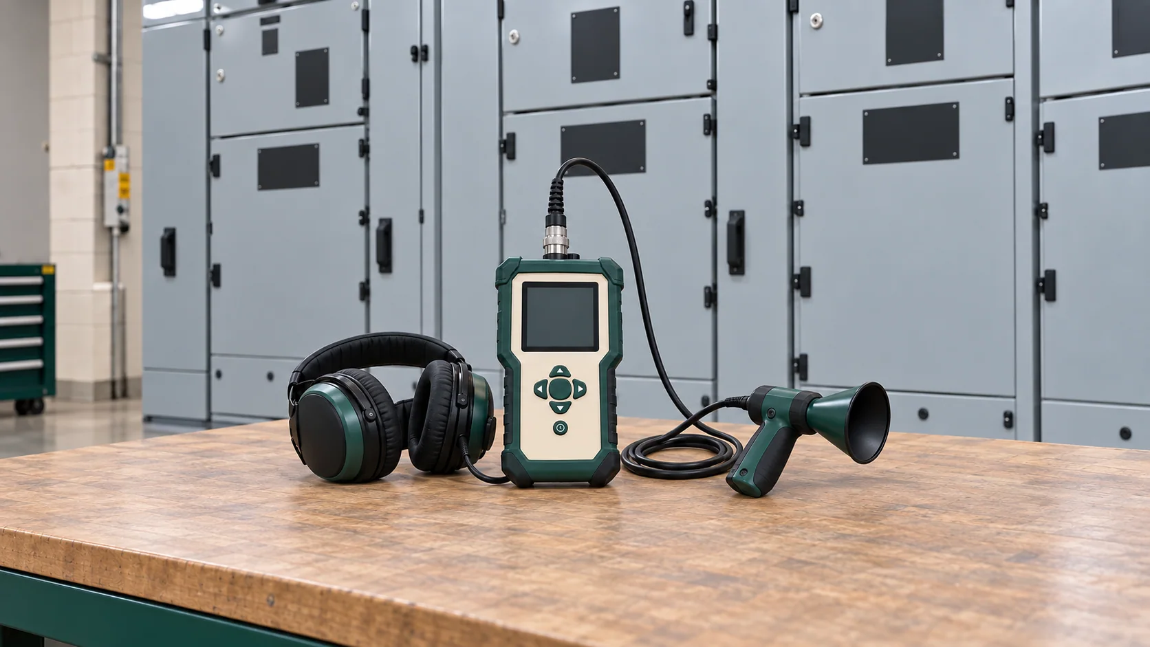
Recognition view: the survey instrument, directional probe and headphones support in-service signal screening while the switchgear remains closed.
01 · What the instruments are detecting
A localized discharge can release energy along several signal paths.
Partial discharge affects only part of the insulation between conductors or between a conductor and earth. The activity may create pressure waves that become ultrasound and short electromagnetic pulses that couple through suitable asset structures.
The diagram separates those possible emissions. Each sensor sees only the energy that reaches its supported path, and an ultrasonic source still requires electrical confirmation.
What happened
Localized electrical activity occurred inside one represented insulation boundary.
What travels
Acoustic and electromagnetic energy follow different paths through air, insulation, conductors and enclosure surfaces.
What the survey records
One sensor-specific view of that activity, attached to a named position and operating condition.
IEC 60270:2025 addresses charge-based partial-discharge measurement and interference discrimination. IEC TS 62478:2016 covers electromagnetic and acoustic methods, including their sensor and sensitivity considerations.
02 · Different sensors see different boundaries
The asset and required evidence determine the sensing method.
Portable surveys often combine methods because switchgear construction and discharge location affect which signal reaches an accessible sensor. Each record retains its own units, coupling conditions and limitations.
01
Airborne and contact ultrasound
Signal observedHigh-frequency acoustic energy that travels through air or through a solid surface to a suitable probe.
Where it fitsAirborne probes support directional screening around accessible external surfaces. Contact probes can carry vibration from a closed enclosure or asset surface where the method is supported.
BoundaryAir leaks, friction, vibration and ambient activity can also produce ultrasound. Frequency selection, background comparison, repeatability and a second evidence source matter.
02
Transient earth voltage (TEV)
Signal observedShort electromagnetic pulses that can couple onto the outside of suitable metal-clad switchgear.
Where it fitsA compatible surface sensor can compare bays and retain pulse activity without opening the enclosure.
BoundaryEnclosure construction, sensor contact, interference and the signal path affect sensitivity. TEV does not represent every discharge location or every asset type.
03
HFCT, UHF and charge-based methods
Signal observedHigh-frequency current, ultra-high-frequency emissions or apparent-charge activity through a method designed for the asset and question.
Where it fitsThese approaches support specialist confirmation, permanent monitoring or deeper diagnosis when the installation provides the required access and coupling point.
BoundaryTheir units, sensitivity, calibration and connection boundary differ from handheld ultrasound and TEV screening. Results cannot be merged as though they were one universal scale.
03 · Reading a screening record
Location and pulse timing answer different parts of the investigation.
The first view places a relative ultrasonic source on a visible switchgear reference. The second places repeated pulse activity across one alternating-current cycle. Read the source marker first, then the grouped pulses, and finally the scattered background points.
Source marker and frequency band
The marker identifies where the selected ultrasonic band appears strongest in the visible field. It supports localization within that observation geometry.
Relative signal level
The displayed level belongs to the sensor, distance, gain, frequency selection and path. It is most useful when compared with a repeat capture or suitable reference.
AC phase and pulse grouping
The horizontal axis follows one 0°–360° supply cycle. Repeated clusters at similar phases can strengthen an electrical interpretation when the instrument and method support phase-related analysis.
Decision value
The combined views can justify repeat screening, comparison with neighboring assets or a second sensing method. They do not identify the physical defect or remaining life automatically.
The map, pulse positions and levels are illustrative and follow common acoustic-imaging and phase-related display conventions. No universal severity threshold or manufacturer-specific diagnosis is shown.
04 · Separating a signal from background activity
A credible indication retains the conditions that made it repeatable.
A single elevated level may come from another asset, ventilation, an air leak, friction or transient interference. The signal identity becomes stronger as the survey fixes the position, captures the background and adds independent evidence.
01
Repeat the observation
The indication recurs at the same asset area under a documented sensor position, frequency range, gain and operating state.
Repeatability separates a persistent source from a single accidental capture.
02
Record the background
Nearby non-asset activity and quieter reference bays are captured with the same compatible setup.
The comparison reveals whether the signal is local to the named asset or present across the environment.
03
Check operating context
Asset voltage, load, switching state, weather or ventilation activity and survey time remain attached to the capture.
A later reader can judge whether two records represent comparable conditions.
04
Add an independent clue
A second suitable sensor, phase-related view, specialist measurement or qualified inspection tests the leading explanation.
Agreement between independent evidence raises confidence; disagreement redirects the investigation.
05 · Private-substation example
One switchgear bay remained distinct through repeat screening.
A commercial property included its private medium-voltage substation in a planned condition survey. The same route and compatible setup were used across four closed bays. Bay 3 produced a localized ultrasonic indication that repeated while neighboring bays and the ambient reference remained quieter.
A compatible second sensing method concentrated activity around the same bay. That agreement raised confidence enough to plan a qualified inspection during an outage; it did not establish the physical condition by itself.
What the evidence supported
The repeated location, quieter references and second sensing method justified a planned inspection of one bay. The team could focus the outage scope and preserve why that area received priority.
What remained open
Qualified inspection established the actual insulation or connection condition. After correction and restoration, a comparable survey checked whether the localized signal recurred.
The scenario and all signal displays are illustrative. Actual access, equipment construction, risk controls and confirmation methods govern the site decision.
06 · Decisions supported
Screening evidence can focus inspection and outage planning.
The practical value lies in deciding which asset deserves closer attention, which confirmation method fits, and whether corrective work changed the observed condition. The signal remains tied to its method and boundary throughout that process.
01
Recorded evidenceOne switchgear area produces a repeatable ultrasonic indication above the recorded local background.
Investigation or actionPrioritize localization and compare neighboring bays before planning intrusive work.
VerificationRepeat the same route and capture conditions, then preserve the position and signal record.
02
Recorded evidenceUltrasonic and compatible electromagnetic evidence remain concentrated around the same named bay.
Investigation or actionEscalate the asset for specialist review and plan a controlled inspection window around the supported location.
VerificationDocument the physical finding during qualified inspection and retain which screening evidence led there.
03
Recorded evidenceA strong ultrasonic source follows ventilation or mechanical operation and lacks a compatible electrical pattern.
Investigation or actionInvestigate the identified acoustic source without labelling it as discharge-related activity.
VerificationRepeat the survey after the source or operating state changes and compare the signal location.
04
Recorded evidenceThe confirmed condition is corrected during a planned outage.
Investigation or actionRestore the asset under the approved method and repeat the justified screening route.
VerificationCompare like-for-like captures and record whether the localized signal recurs.
07 · Choosing equipment
Sensor coverage and retained evidence shape the equipment choice.
Directional ultrasound, multimode partial-discharge survey tools and acoustic imagers overlap in some applications. Their sensing modes, display conventions, accessories and reporting depth differ by model.
Equipment family
Where it fits
Selection checks
Neutral examples
Indicative hardware
Directional digital ultrasonic screening kit
General condition screening for airborne or structure-borne ultrasound where location, audio and repeatable level records support the maintenance question.
Confirm frequency range, probe types, headphones, data storage, reporting, calibration and whether electrical-discharge analysis is actually supported.
UE Systems Ultraprobe 3000, 9000, 10000 and 15000 families.
30,000–90,000 MAD
Multimode TEV and ultrasonic PD survey kit
In-service screening of suitable switchgear using built-in or compatible TEV and ultrasonic sensing with optional specialist inputs.
Confirm sensor set, phase reference, PRPD or waveform capability, asset compatibility, software, function checks and package contents.
EA Technology UltraTEV Plus²; IPEC PD Detector Pro.
80,000–160,000+ MAD
Acoustic imaging camera with PD capability
Wide-area ultrasonic localization where a sound map helps screen complex or less accessible equipment from an approved observation position.
Confirm usable frequency range, PD mode, distance limits, acoustic environment, image export, batteries, software and training.
Fluke ii915 and comparable industrial acoustic imagers.
220,000–300,000+ MAD
Directional digital ultrasonic screening kit
General condition screening for airborne or structure-borne ultrasound where location, audio and repeatable level records support the maintenance question.
Selection: Confirm frequency range, probe types, headphones, data storage, reporting, calibration and whether electrical-discharge analysis is actually supported.
UE Systems Ultraprobe 3000, 9000, 10000 and 15000 families.
30,000–90,000 MAD
Multimode TEV and ultrasonic PD survey kit
In-service screening of suitable switchgear using built-in or compatible TEV and ultrasonic sensing with optional specialist inputs.
Selection: Confirm sensor set, phase reference, PRPD or waveform capability, asset compatibility, software, function checks and package contents.
EA Technology UltraTEV Plus²; IPEC PD Detector Pro.
80,000–160,000+ MAD
Acoustic imaging camera with PD capability
Wide-area ultrasonic localization where a sound map helps screen complex or less accessible equipment from an approved observation position.
Selection: Confirm usable frequency range, PD mode, distance limits, acoustic environment, image export, batteries, software and training.
Fluke ii915 and comparable industrial acoustic imagers.
220,000–300,000+ MAD
Indicative July 2026 MAD equivalents for hardware acquisition, using approximately 1 EUR = 10.71 MAD and 1 USD = 9.13 MAD. VAT, import, transport, specialist sensors, software, licenses, calibration, training and professional analysis may be excluded. Specialist UHF, HFCT and charge-based systems remain separately scoped.
The survey packet preserves the route, sensor and evidence identity.
A useful package extends beyond the instrument body. It includes supported sensors, listening or visualization accessories, power, storage, software, asset references and calibration evidence that match the intended survey.
Surveys occur around energized equipment under approved access and safety controls. Qualified personnel select positions, coupling methods and settings. The record below describes responsibilities and deliverables without providing live-survey instructions.
Question and route
Named assets, accessible observation boundaries, operating consequence, route order and reference bays.
Complete kit
Main instrument, supported ultrasonic and/or TEV sensors, headphones where applicable, power, storage, software, asset register and calibration record.
Method-dependent additions
HFCT, UHF, contact or directional probes, phase reference, remote sensors and specialist analysis software only where the selected method requires them.
Capture identity
Asset, enclosure surface, sensor type, position, distance or coupling, frequency band, gain, time, operating state and background reference.
First useful analysis
Whether the signal repeats, where it is strongest, how it differs from background, whether another modality agrees and which next action is justified.
Handover
Original captures, route, settings, interpretation, confidence, planned inspection, physical finding, correction and comparable resurvey.
09 · Report and review
The report keeps every indication attached to its sensor and position.
An isolated level or screenshot cannot reconstruct the survey. The retained record lets another qualified reader see what was observed, how the background was handled and why the proposed action follows.
Asset and boundary
Site, substation, bay or asset identifier, enclosure state, observation surface and survey route.
Instrument and sensor
Instrument, firmware where relevant, sensor or probe, serial record, function check and calibration status.
Capture conditions
Frequency band, gain, position, distance or coupling, operating voltage/load, time, weather or ventilation context and background reference.
Evidence retained
Audio or source map, relative level, TEV/RF record where used, phase-related view, repeat captures and neighboring references.
Interpretation
Supported signal identity, confidence, alternative sources, inaccessible boundaries and confirmation still required.
Action and verification
Inspection priority, outage or specialist plan, physical finding, corrective work and comparable post-work survey.
Practical FAQ
Questions that often remain after a discharge-screening proposal.
These answers clarify instrument overlap, in-service access, background noise and the limits of a clear or elevated indication.
Some ultrasonic instruments support discharge screening, while general ultrasonic detectors also serve air-leak, mechanical and lubrication work. A multimode partial-discharge survey instrument may add TEV, phase-related analysis or compatible specialist sensors. The required signal and evidence determine which instrument family fits.
Many screening methods are intended for in-service observation from approved accessible positions. The site risk assessment, equipment construction, access boundary and instrument method govern whether and how a qualified survey proceeds.
Thermography records apparent surface-temperature patterns. A discharge-related condition may produce little visible heating, while a thermal exception may have another cause. The two methods provide different evidence and can complement each other when the investigation justifies both.
Yes. Compressed-air leaks, friction, vibration and other ambient sources can produce ultrasonic energy. Frequency selection, directional checks, neighboring references, repeat captures and another compatible sensing method help distinguish the source.
No. Signal strength belongs to a sensor, position, gain, path and operating condition. It can support location and inspection priority; qualified confirmation establishes the physical condition, and the record does not calculate remaining life by itself.
No detected indication means that the selected method found no reportable signal within its sensitivity and accessible boundary at that time. Other discharge locations, operating states or insulation conditions may remain outside that record.
Conclusion
What credible discharge screening makes possible.
A well-documented survey can reveal a repeatable signal, show where it is concentrated, distinguish it from nearby background activity and provide evidence for a targeted inspection or specialist measurement.
01
Screen suitable assets without waiting for a complete failure.
02
Focus attention on a repeatable source area.
03
Plan confirmation and outage scope using recorded evidence.
04
Document the physical condition found during inspection.
05
Verify whether the signal recurs after corrective work.
Screening does not identify every physical defect, calculate remaining insulation life or prove that an asset is healthy. Its value comes from a suitable sensor, a named boundary, background discrimination, qualified confirmation and a comparable post-work record.
Insulation-condition evidence
Have a partial-discharge survey or signal record to review?
Send the asset list, equipment type, proposed sensing method, captures or existing report. ReneWave can explain what the signals represent, which validity conditions matter and what confirmation should follow.