Earth Resistance and Loop Impedance Testing: What Each Measurement Can Reveal
Earth resistance testing examines an electrode and its relationship with the surrounding soil through a selected method. Loop impedance testing measures the complete fault-current path represented at a named installation point.
Both records concern protective paths. Their boundaries, methods and interpretation remain separate, and qualified verification determines how they are assessed against the actual installation design.
Earth electrodeFault loopMethod selection
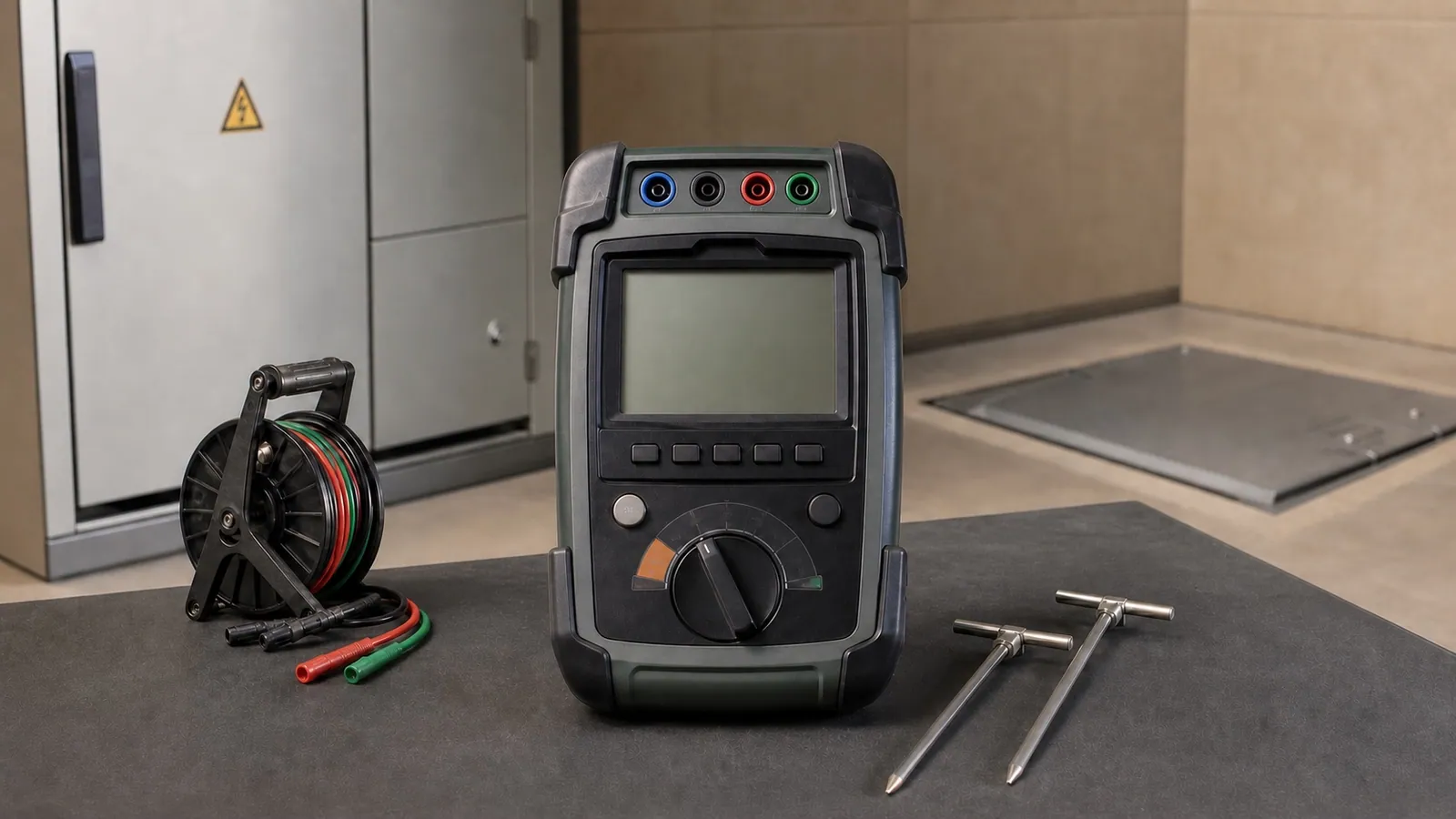
Recognition view: the multifunction tester is the main instrument; the smaller reel and two stakes indicate the separate earth-resistance kit used when the selected method requires it.
01 · Two measurements on one protective path
The test boundary determines which part of the path the result represents.
A fault-current path may include the source, line conductor, remote equipment, protective conductor, main earth connection, electrode and the source return. Earth resistance and loop impedance describe different portions of that system.
The diagram identifies physical roles only. It omits terminals, connection locations and procedures.
Protective-conductor continuity
Examines the continuity or resistance of a named protective conductor or bonding path using its applicable method. It does not replace the complete loop or electrode record.
RCD testing
Examines the response of a residual-current device under the selected verification method. Loop and RCD evidence may both matter, but they answer different protection questions. Read the RCD and leakage article.
IEC 61557-3:2019 covers loop-impedance measuring equipment. IEC 61557-5:2019 covers equipment for measuring earth resistance. IEC 61557-4 and IEC 60364-6 provide related protective-conductor and installation-verification context.
02 · Selecting an earth-test method
The installation geometry decides which earth method can produce a credible record.
Auxiliary-stake, selective-clamp and stakeless methods do not observe the same arrangement under every site condition. The proposal should name the method and explain why the electrode, connected paths and available space support it.
01
Fall-of-potential method
Record and fit
A dedicated earth tester uses an approved auxiliary-electrode arrangement to record resistance as the potential probe position changes. Useful when the electrode can be separated sufficiently from parallel paths and the site provides the space and access required by the selected method.
Validity boundary
Probe geometry, buried services, interference, soil conditions and incomplete separation can weaken the record. The article does not provide stake-placement instructions.
02
Selective-clamp method
Record and fit
A compatible clamp isolates the current associated with one electrode or path while the approved test arrangement remains connected to the wider earthing system. Useful where disconnecting the selected electrode would be disruptive and the instrument, clamp and installation arrangement support the method.
Validity boundary
The result depends on the available return paths and the exact system geometry. A clamp accessory does not make every connected electrode measurable by this method.
03
Stakeless two-clamp method
Record and fit
Two compatible clamps drive and measure a signal around an existing conductive loop without auxiliary stakes. Useful only where the earthing network provides a complete parallel return path that satisfies the instrument method.
Validity boundary
It measures the loop available to the clamps, not an isolated electrode by itself. A simple or single-path electrode arrangement may not support the method.
Official Fluke 1625-2 and compatible Megger and Chauvin Arnoux documentation describe fall-of-potential, selective and stakeless capabilities as model- and accessory-dependent. The actual procedure remains controlled by the selected instrument method and site conditions.
03 · Reading the earth record
A stable region helps show whether the selected arrangement isolated a usable result.
For a fall-of-potential record, the horizontal direction represents the potential probe’s position along the approved test line. The vertical direction represents the measured resistance in ohms. The curve is reviewed for a comparatively stable region away from disturbed positions.
The illustrative shape explains method stability. It does not prescribe probe spacing or provide a universal acceptable resistance.
Electrode identity
The report names the electrode or earthing subsystem, its connected state and the exact method represented.
Position stability
Several positions or checks support the reported result; one convenient display value cannot demonstrate the stable region by itself.
Site context
Soil condition, recent weather, interference, buried infrastructure and parallel paths remain attached to interpretation and future comparison.
04 · Reading the loop record
A loop result belongs to one named point and its protection context.
Installation testers commonly retain a numeric loop impedance in ohms and may calculate prospective fault current from the recorded values. The point, earthing arrangement, circuit state, selected method and protective device decide how the number is assessed.
Measurement point
Cooling plant DB · outgoing feeder CP-02
Recorded fields
Loop impedance (Ω), prospective fault current where supported, phase/point and timestamp.
Method context
Earthing arrangement, circuit state, selected tester method and any RCD-related constraint.
Protection reference
Protective device, circuit design information and applicable verification basis.
Interpretation boundary
The point record can narrow a path concern. Inspection or additional point measurements confirm the physical condition.
All report fields above are illustrative. No universal loop limit, prospective-current requirement, disconnection time or earthing-system rule is presented.
05 · Commercial-property example
Civil work and a feeder modification created two separate verification questions.
A commercial property completed ground work near its main earth inspection pit while a remote cooling feeder was modified. The owner needed to know whether the earth evidence remained comparable and whether the modified circuit preserved a credible protective path.
01
Main earth electrode
The selected earth method produced a stable region and a result comparable with the site’s prior record after civil works near the inspection pit.
The new earth evidence did not indicate a material change at the measured electrode boundary under the recorded conditions.
02
Main LV board
The loop record at the board established the upstream reference for the named cooling feeder and retained the protective-device context.
The source-side evidence gave the investigation a point from which downstream change could be assessed.
03
Cooling feeder distribution point
The named downstream loop result was higher than the main-board reference by an amount that required review against the actual circuit design.
The increase directed attention along the feeder protective path; it did not identify a particular connection automatically.
04
Remote cooling equipment
Qualified inspection confirmed a degraded protective-conductor termination. The same loop point was repeated after correction and restoration.
The retest verified that the measured path changed. The separate earth-electrode record remained unchanged because it represented another boundary.
The scenario and all implied values are illustrative. The actual design, earthing arrangement, protective devices and applicable verification method govern the site decision.
06 · Decisions supported
The records direct attention to the portion of the protective system that changed.
Credible evidence can prioritize electrode inspection, protective-conductor checks, termination assessment, protective-device review and a comparable retest. The method and measurement point prevent unrelated findings from being merged.
01
Recorded evidenceThe earth position record has no stable region or changes materially between repeat arrangements.
Investigation or actionReview method suitability, interference, probe geometry, parallel paths and site conditions before treating the displayed number as the electrode result.
VerificationRepeat the approved method with documented conditions and retain the position evidence supporting the final value.
02
Recorded evidenceA credible earth result changes from comparable site history after corrosion, civil work or environmental change.
Investigation or actionPrioritize qualified inspection of the electrode, connection, inspection pit and associated earthing components within the measured boundary.
VerificationRecord the confirmed condition and repeat the same justified method after corrective work.
03
Recorded evidenceLoop impedance increases between an upstream reference and a named downstream point.
Investigation or actionReview the protective conductor, terminations, circuit length and installation evidence against the actual protective-device requirements.
VerificationRetest the same points after the confirmed condition is corrected and the installation is restored.
04
Recorded evidenceEarth resistance is credible while downstream loop evidence remains concerning.
Investigation or actionKeep the two findings separate and continue the circuit-path investigation. The electrode result cannot clear a remote protective-conductor issue.
VerificationPreserve each point, method and record so the post-work evidence can show which part of the protective path changed.
07 · Choosing equipment
Method coverage and the complete accessory set shape the useful instrument.
A multifunction tester can cover broad installation verification, while a dedicated earth tester may preserve stronger method-specific evidence. Selective and stakeless work depends on compatible clamp systems and a suitable earthing geometry.
Equipment family
Where it fits
Selection checks
Neutral examples
Indicative hardware
Multifunction LV installation tester
Installation verification where loop impedance, protective-conductor continuity, RCD and other supported tests must be retained at named points.
Confirm earthing-system support, loop method, prospective-current fields, RCD-aware options, memory, leads and earth-test accessories where required.
Indicative July 2026 MAD equivalents for hardware acquisition, using approximately 1 EUR = 10.7 MAD. VAT, import, transport, stakes, reels, clamps, specialist probes, software, calibration, training and professional testing may be excluded. A complete working kit can exceed the displayed band.
Examples support recognition and scope review; they are not rankings. Official family references include Megger MFT-X1, Fluke 1625-2, Metrel MI 3155 and Chauvin Arnoux C.A 6117/6470N documentation.
08 · Complete kit and qualified verification
The working kit and retained method must fit each measurement boundary.
The tester body is one part of the job. Leads, reels, stakes, clamps, point records, installation information and calibration evidence determine whether the proposed method can be completed and reviewed.
Earth-resistance work
Typical baseline
Dedicated or compatible multifunction tester, approved leads, suitable reels and auxiliary stakes for the selected method, current documentation, power, memory and calibration status.
Method or package dependent
Selective-current clamp, stakeless drive and sense clamps, alternative stake or reel lengths, interference-management accessories and environmental records vary by method and package.
Loop-impedance work
Typical baseline
Compatible installation tester, rated lead set, point register, earthing-arrangement and protective-device information, current documentation, power, memory and calibration status.
Method or package dependent
Special lead arrangements, remote probes, RCD-aware or low-current methods, software, communications and reporting licenses vary by circuit and instrument.
01
Define each question
Name the electrode or circuit point, the protective-path decision, the earthing arrangement and the evidence required from each test.
02
Select the method and complete kit
Qualified personnel confirm the supported method, tester, lead or clamp set, site geometry, circuit state, protective-device context and calibration record.
03
Establish approved site controls
The work follows the site safety method, manufacturer documentation and applicable verification procedure. This article omits connection and stake-placement instructions.
04
Validate the record
Check point identity, lead or sensor condition, method selection, interference indications, clock, stored fields and whether the live values are plausible for the stated boundary.
05
Interpret without merging scopes
Read the earth result with its method and soil context; read the loop result with its named point, earthing arrangement and protective-device reference.
06
Restore, report and retest
Document restoration, inspection findings, correction, repeated point or method, remaining uncertainty and the evidence supporting the next decision.
09 · Report and review
The report keeps each value attached to its method and point.
A bare ohm value cannot show whether it describes an electrode, a complete loop or another protective-path measurement. The retained record allows another qualified reader to reconstruct what was tested and why the interpretation follows.
Installation identity
Site, distribution point, circuit or electrode identity, one-line reference and earthing arrangement.
Method and instrument
Test purpose, selected method, instrument and accessory references, serial record, firmware where relevant and calibration status.
Earth evidence
Electrode boundary, connected state, probe-position or clamp context, interference indication, soil/weather context and retained result.
Loop evidence
Named point, loop impedance, prospective current where supported, circuit state, method and protective-device reference.
Interpretation
What each record supports, design or procedure used for assessment, comparison history, confidence and unresolved portions of the path.
Action and verification
Inspection, confirmed condition, correction, restoration, repeated point or method and post-work result.
Practical FAQ
Questions that often remain after an earth or loop proposal.
These answers clarify equipment overlap, method limits, environmental changes and what each result can establish.
No. The earth result describes the electrode or earthing boundary represented by the selected method. Protective-conductor continuity, loop impedance, protective-device behavior and the condition of downstream connections require their own applicable evidence.
It can when the exact model, leads, clamps and accessories support the required earth method and loop method for the installation. A tester body sold without the applicable earth kit or method capability may not provide both records.
No. Clamp and stakeless methods require a suitable connected return path and instrument-supported geometry. An isolated electrode or simple single-path arrangement may require another approved method.
Soil moisture, temperature and the current distribution around an electrode can change the measured resistance. Useful comparisons retain weather and soil context and use a consistent justified method rather than treating every difference as electrode deterioration.
The selected tester method and qualified verification plan must suit the circuit and protective device. Some instruments provide methods intended to reduce unwanted RCD operation, but their applicability and interpretation remain model- and installation-specific.
No. A point-to-point change can narrow the affected portion of the protective path. Qualified inspection, continuity measurements or other applicable tests establish the physical condition and confirm the corrective scope.
Conclusion
What credible earth and loop records make possible.
Earth resistance evidence can show whether a selected electrode method produced a stable, comparable result. Loop impedance evidence can show how the complete fault path behaves at named points and where a meaningful change appears along a circuit.
01
Preserve the electrode and circuit boundaries.
02
Prioritize inspection where the evidence changes.
03
Review protection against the actual installation design.
04
Retest the same point or method after confirmed work.
05
Keep restoration and uncertainty in the final record.
Neither result automatically locates a defective connection, proves every protective function or replaces the applicable design and verification review. Their value comes from a clear boundary, a justified method, qualified interpretation and comparable post-work evidence.
Protective-path evidence
Have an earth or loop test proposal to review?
Send the site arrangement, tester scope, earth method, point list or existing results. ReneWave can explain what each record represents, which validity conditions matter and what should remain after verification.